The gpio expansion is on the jackpot, right? Does the pico klipper firmware need to be edited to support that? Can you easily customize the pico firmware so the other pinouts go to the right pins? Or are you planning on doing all that making in the daughter board?
Are there other fluidnc specific pin hacks, like combining endstop pins that wouldn’t work with the klipper firmware?
Trying to poke holes now. Editing firmware is easier than writing new firmware. But it would be nice if you could just drop it in.
Yes. The first three 2209s share one device ID, and have a funky scheme to let them share that by use a 74HC4066 as gate to let the ESP32 UART through to those TMCs. There is a pecularity of the 2209s where they start pulling the UART (BOOT pin on ESP32) down too far. So, the next three 2209s then get their own unique IDs (any more than 3 and the board wouldn’t boot reliably- at least before Ryan added the extra boot0 pullup on the jackpot.)
This scheme isn’t present in any Klipper implementation that I’ve found so far. I’m not sure if support for this has to be in the klipper MCU code (I think it must) or if it can live in the host controller- but either way it is unique and new implementation to create.
Similarly, all 6 of the drivers individual step, direction and enable pins are multiplexed through a serial chain of 74AHCT595PW I2S parts. I’m just starting to look that over and see if there might be a comparable implementation in another Klipper MCU.
So far, I’ve only found one example of a Klipper printer board that is using RP2040, the MKS Pico. That has 2209s, but does not use the UARTs (Which is a crime!). I’ll be studying that more.
The other RP2040 implementations that I see are to do things like CAN bus, or accelerometer interfaces, or toolhead breakouts.
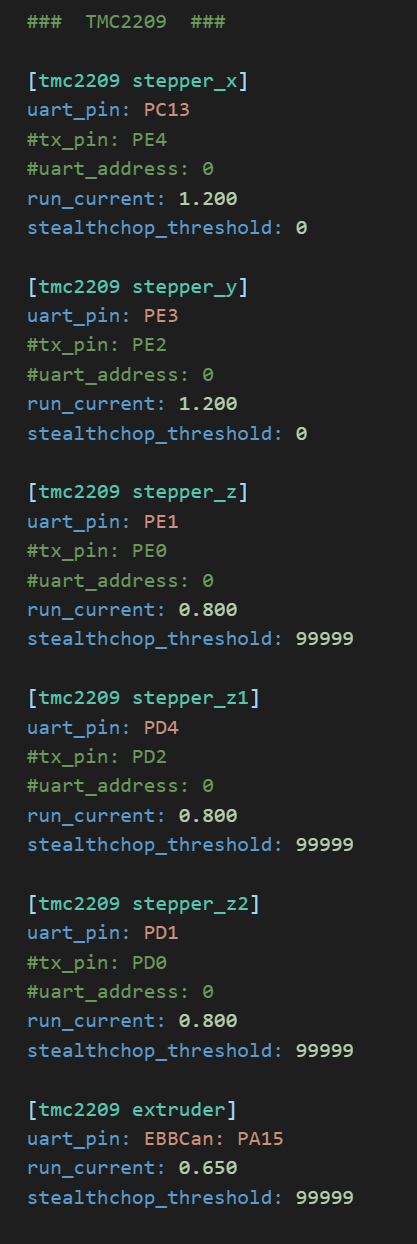
This may not help at all, but just incase here is a screen shot of my 2209 config for the V4. I don’t give it any uart address at all. I actually thought I had to because of the way it is on my SKR Mini E3 V3 which also has 2209s but soldered to the board. Those all get the address line and are addressed 0-4 (only 4 drivers on that board)
The SKR Mini E3 V3 uses an STM32F40 microcontroller, and like the MKS Pico it uses TMC2209 drivers, but does not connect the UARTs (!!!)
What a crime.
As an example, you can’t change the driver motor current setting on that board except by adjusting the pot on the TMC driver.
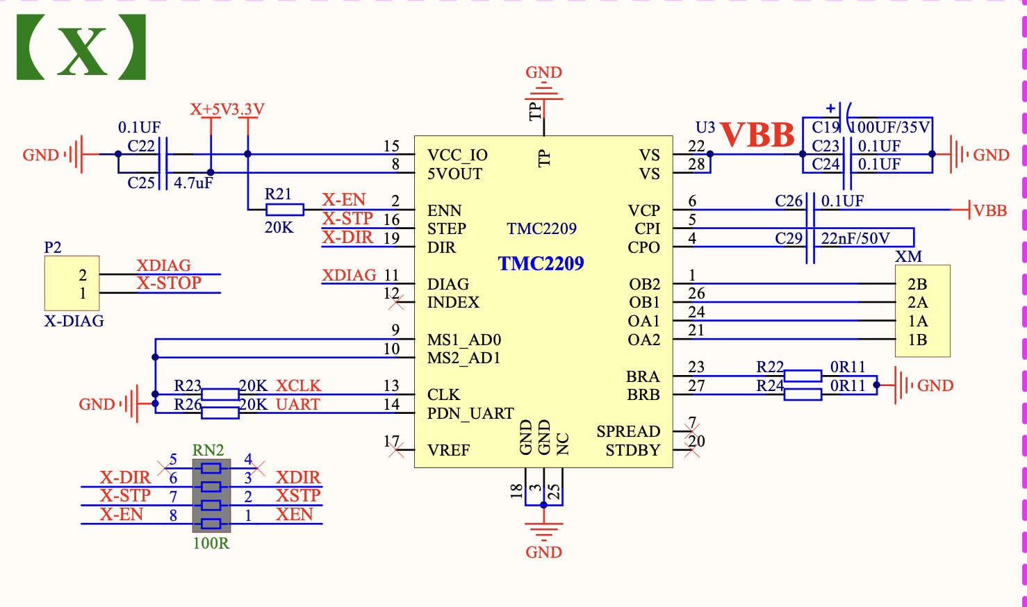
Below shows how the TMCs are connected on that board (MKS Pico is similar, just uses an RP2040)
UART would be pin 14, and instead is pulled to ground through a 20K ohm resister.
Incase I wasn’t clear before the config I posted was from my SKR Pro 1.2 that doesn’t use address and also has the plug in style 2209s like the jackpot. Now again none of that probably matters for this case but just incase it did I wanted to share lol
(Technically, this is an old config, but I didn’t want to get up to find the newest version).
I agree with you Mike, having TMC drivers and not talking to them is one of those things that really bothers me. It gets the TMC bullet and there are some advantages to them as standalone. But I hate that some people will think they are getting all the benefits when they are not.
Is there a specific comparable controller board (mostly used for 3D printers) that you’re looking to beat on features/price? Are Touch Screen, WebCam, adxl345 input shaping, and/or CAN Bus support required, or optional features?
Personally, I’d also want CAN Bus on a future build. That’s despite the initial PITA setup, and PITA upgrade for protocol breaking changes.
Curious if the expected savings end up being a foreseeable significant fraction of the overall BOM cost. Regardless of the savings, you might want to make a daughter board or another main controller board optimized Printers anyway, for the fun, the experience, or supply chain redundancy/other reasons.
Asking about goals because bang for buck and flexible design was mentioned as MP3DP v5 goals. Controllers with extra driver slots and connectors for things like ERCF MMU mod seem to be reducing in price…
Am catching up… But sounds like you’re collectively converging on…
Only the Pi running MainSail, Klipper Host needs WIFI, so…
Even if ESP32 was able to run Klipper firmware, then WIFI would be disabled anyway. In which case may as well use a cheap powerful enough reliable available controller already supported by Klipper (Features - Klipper documentation).
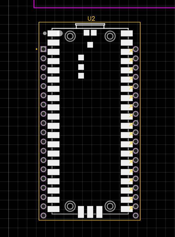
Q: Is that a RP2040, or some STM32…, or something else with enough GPIO that could be packaged into a ESP32 Dev kit compatible pinout, so that existing JackPot boards can be leveraged?
Do this and you’ll have a Klipper drivable ESP32 Dev kit pinout compatible board that can be used in other scenarios, by other people too…
If using RP2040 on a daughter, or new main board, would you use Raspberry Pi Pico boards, or add Pico chips directly to your PCB design e.g. RP2040 from LCSC? Pico chip package looks tiny, hope layout and fab are reliable.
Maybe you prototype with RP2040 board, and work towards a PCB if/when have end-to-end functionality working, parts costed and pros/cons/caveats figured out?
I don’t think we have any endstop pins combined. So hopefully there are no other tricks The tmc expander is the only one I am really worried about.
oooooohhhh shoot
Double oooh shooot.
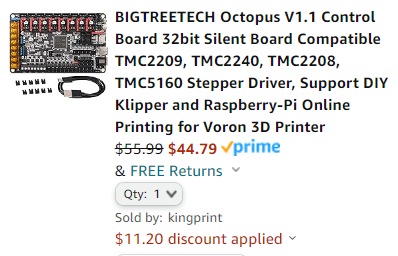
Nope, the more jackpots and drivers we buy the more the price drops.
Maybe after I make a new LR, Zen, mpcnc…and finish this new printer. I love making boards…but it is #2 on my list of things I like releasing.
That is a cool thought. I wonder how often this might happen.
Yes. With the cost of the full pico boards, they do not seem to have the markup of the espresiff. It would be very hard to even match the price, so the only reason to redo it would be to save room or change the footprint I would think.
I don’t have to make any of that type of klipper choice, the end user can pick whatever they want to use I would think.
My plans was to breakout the pins to all the similar places. UART capable, analog capable, try to match pin for pin what each board can do in a sensible way, then see if klipper needed any specific pin for any specific purpose and route it there. Then have you guys check my mowrk / notes.
At that point we can figure out is the ESP32 or adding the expander to the pico is the easier path forward. Then I will see what I can do to entice someone to help forge ahead.
As far as screens, canbus and any of that. As long as we get the jackpot running klipper then all of that can be the same as it is now with any other board. You wont have the can bus bridge on the board but you can use a U2C like any other board would. Also klipper screen and accelerometers will work from the main Pi as well. So really as long as we can get basic klipper to work on the jackpot then the world of klipper is all there and ready
We can route traces on either side, but need to make sure all components are on one side. Matter of fact if the pico is on the bottom (upside down) it will be even cheaper to make.
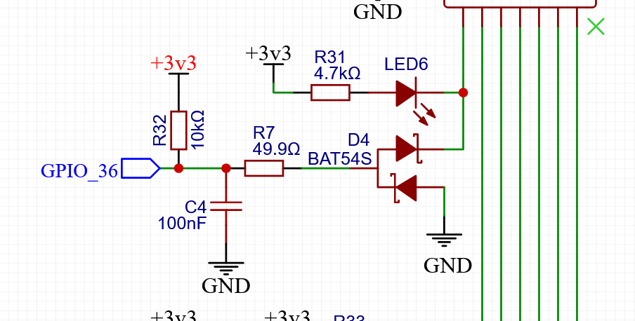
Okay so I am looking at it now. Why can’t we do thermistor signals through the Schottky diodes? Do I even need to break out naked input pins?
The Jackpot
-Vmot outs, handle two fans (print and extruder)
-5V out handle two SSR’s - bed and hot end
-7 inputs - touch probe, bed therm, hotend therm, X endstop, Y endstop, two spare inputs.
-expansion port gives us 4 naked GPIO
If the pico is on the bottom (or if you design your own RP2040 board and don’t buy a full pico), then on the top maybe you could put headers and electronics for the themistor and bed FET interfaces- if it’s going to be a printer add-on board maybe that makes some sense. I need to think about that a bit. But if you just see the V1 RP2040 widget in ESP32 packaging as a bolt-on to enhance your existing klipper installation maybe that makes sense in its own right. Regardless of whether or not it lives on a a Jackpot.
You keep leaning to not using the ports that are already available. What am I missing? Remember, I have little to no EE experience. It might seem obvious to you but I really don’t understand why not.
Can we use the thermistors through the diodes that are there? Or do I need to break out two extra naked IO.
I can’t imagine wanting to add Vmot header, and jumper wires to the add on board just for a hotend FET, why not just use a SSR. We need one for the bed anyway, and they are cheap.
typically thermistor input is analog and I’ve never seen it gated with a diode. You will need to power one leg of the the thermistor with your pico board power, then put a bridge resistor to ground off of the sense leg. The resistor value will be key here. There should be documentation from other boards for how this is done.
Okay, I just tried it with a meter in the esp port without the esp there. I assume, that gives the reading? Seems like the diode is less of an issue and the resistors are the issue? Or when power is applied to the LED things will change?