It feels like I’ve come back home to V1 just in time for some amazing advancement in the Low Rider department and so, in anticipation of the release I’m starting to plan and gather the “needs”. Here’s the start of something hopefully very useful for me in the ice carving world (and at home in the shop).
Capacity: 20 inch working width, maybe up to 40 inch travel
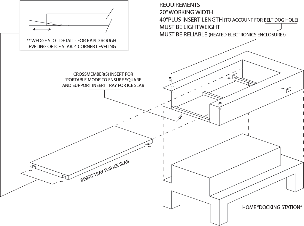
Primary wish: Portability
The thought: Create a U-Shaped rigid structure for the LR3 to ride on. Ice slabs can be slid into the ‘void’ and machined.
Specific needs:
a way to keep the electronics warm
protection from snow for the steppers
gantry mounted air assist with a high pressure pulse blast, maybe 3 per second (steady stream would tax even my giant compressor)
a way to quickly level what is sure to be a not so perfect slab of ice (I don’t want to have to do a surfacing pass)
Here’s the start to the “Docking station” thinking. If anyone thinks I’m looking at a few trips to the impossible store please let me know! Now how do I add a picture again?..
This is amazing, well put together. I don’t think I want that much assembly and fine tuning if I can get away with it. Storage, while it would be nice is not a huge concern for me. But man, so well built. I dig it.
You know I have a leveling set of instructions in the works, you could pretty quickly level the X axis depending on how much Z you can sacrifice. The Z is pretty much fixed travel this time, it would take a bit of editing to add more, and it is not really set up for more.
For the Y the wedges might be better on the table instead of the block. I imagine the block is more fragile than the table?
I was thinking of that portable build while we were talking. It’s definitely a possibility, but the LR3 doesn’t have some of the constraints that made that build’s complexity a necessity. Gotta keep that darn cat in the bag a little while longer, though, so I don’t want to be too specific. The general idea can still be the same, but some of the parameters change for the machine mount surface.
Keep in mind that the rolling surface has to be longer than the work surface, by a little under the LR2’s current need of 11" so you’ll need to indent that ice tray into the machine area by a little.
Having the main piece like that as one unit does limit portability, I think. That piece is going to need to be a little under 5’ long and (for a 20" wide build width) … Well, less than 3’ wide. Maybe that’s not too bad, but definitely a 2-person lift. Using registration bolts for the crossmember spars would probably be adequate for making the sides parallel, but squaring would be a little sketchy, I think. I’d worry about torque on the “bottom” of the U shaped piece some. There could be an awful lot of force there, and you don’t want to make it too heavy.
I still kind of like the idea of using the truck bed as a superstructure. Each piece then only need to be about 14-18" wide and you’ll have a more or less guaranteed square and parallel pair of sides to mount the rolling machine on. The parts can be lightweight. Even if you don’t have the mounting togs that “regular” pickup trucks do, there will be something that can be done… After all, you have a CNC machine that’s capable of making whatever pieces you need to make the mounts.
I’ve already done the edits to add 50mm more Z. Unlikely that I’ll ever really need it though.
I see that diagram as having the wedges under a “tray” that sits under the ice. Maybe a double piece of 3/4" material that will support the ice and slide out of the machine once the carving is complete. If that’s the case, I might want to leave room for handholds and maybe even a lip around the ice so that it doesn’t slide off. Those are just details though.
The current “ice sled” that hides under the table insert of my MPCNC is kinda what I’m thinking for that on-site insert piece. When we ran ice in there we literally just used those plastic building shims under whatever part of the ice needed support or lifting. I just kinda figured that in this case maybe I could wedge level a table insert (once the ice was in place) rather than wedging the ice itself. In either case each piece of ice needs to be wedge levelled. But it’s not critical to be dead accurate. The side we carve into is the backside to the public.
It would be handy to have a file I could run that would jump to the four corners and maybe a few mid point spans but I KNOW this is doable. Previously I’d just roll the gantry around and check here and there. But the LCD always lit up to remind me not to roll the gantry around too fast. Hahaha
I figured I’d need more than 40" but wasn’t sure how much. Those measurements will come I know (how long and wide overall, how wide each side of the setup needs to be etc.). Truth be told we don’t cut right to the 20 or 40. We have to stay at least 2" from the edges or we get stress fractures when the ice starts to temper to its new shape. So really I only need 18 by maybe 35? But it’s still nice to be able to draw a clean 19 x 38 rectangle that I can use as a guide for the chainsaw when assembling stuff. That was critical on the Muttart project.
One other thing about the leveling of the ice. We do sand it down nice and true/flat before engraving but it could still be as much as an inch? in thickness variance depending on how much we drank the night before. So to level it much like a print bed using wedges works just fine. We also just screwed blocks down to the tray and used more of those shims to “lock” the ice in place. On two perpendicular sides. The other two sides were up against the drop walls under the table insert at “0,0” as it were. This build I’d like to incorporate something a little more purpose built as opposed to “do you have any scrap 2x4?”.
I like the plan. I think you can get by with a lot less chunk on the U part. In my experience, 3/4" plywood joined on three sides of a corner is super strong. It you build the back piece, the bottom piece, and the side pieces out of something like that, it will be strong enough to stand on. The CNC will have no problem riding there. You will probably need to seal the crap out of it, and the edge of plywood may be insufficient for the CNC to ride on. So you may still want to incorporate something on the top. Adding that to the corner would make it even stronger.
I’m curious about the 3Hz pulse on the air blast. Are there devices set up to do that already? Or do you have to quickly toggle a solenoid? I am not sure how fast or how long you are supposed to toggle solenoids. Obliviously, things like pneumatic tools do just fine. So something must exist.
My guess is the electronics will work fine at low temperatures. They will generate their own heat too. The real worry is the water. Sealing them will make them heat up quicker (I’m imagining a bunch of silicone and a Tupperware). I wonder if you could build a sort of open box with a slanted roof for them to live in where they can vent, but still have the water fall off without going in the box. Or maybe move all the electronics under the bed, and direct all the water forcefully away.
The steppers also warm up a lot. Both ends of the shaft are open and there are bearings and magnets you don’t want corroding. I wouldn’t be surprised if the stepper electronics were waterproof, but someone must have already tried that and found out. Maybe you could put them in a deflated balloon and just seal the wires with hot glue or silicone (maybe not hot glue, because of the heat) The front end is going to have to be open for the shaft. But maybe it can be an undersized hole and it will work for a while, at least?
I don’t see any problem with a U shape though. Especially if you can connect under the front side. It will be as rigid as any table. You must have already seen what water and ice and the electronics do.
I never had any real issues no. The LCD refresh was terrible though. As much as I lusted after the big screen on Dan’s machine in the back of my mind I kept thinking about that.
I covered the steppers on the MPCNC with baggies and tape. It was tricky but did the trick and never snagged. Looking at Dan’s build we discussed waterproofing. It’s already a step ahead because the steppers are partially shielded behind the side plates. Sealing the rest should be no problem. Well, I shouldn’t say “sealing”……protecting maybe is a better word.
Yes, I think you rescued me one of the last times I used the MPCNC for ice. The board got wet and the machine died. Luckily it dried out and wasn’t fried.
As for the plywood and proportions. Those dimensions will come. I’m certain the width to height ratios in my doodles are way outta whack but good to know you think plywood would be rigid enough. I spent some time today looking for a good source for extrusion thinking that might be best here but hard to find any that doesn’t cost more than a sauna. We don’t have many options here in Canada I don’t think. I have a customer that I’ll see on Wednesday that built one of the extrusion based CNCs (can’t recall which……I think it used 80/20?). Anyway, I’ll ask where he ordered from. Maybe he found a cheap source.
Rounding back around the bend to this one here. Hope to connect with Dan for another look at the LR3. I’ve been thinking about the initial thoughts I had above including the leveling wedges, the plywood construction materials, the docking station plan.
The knock down plan would be to lift the LR3 off and stow it, but then I’m left with a giant, boxy plywood “U”. I like Heffe’s comment about not needing to box it right in. You’re absolutely right there. I wonder if I could build two logs and eliminate that connecting box portion altogether? So it’s no longer a “U”. Could be disassembled to pretty much the LR3 assembly, the left hand box/platform and the right hand box/platform. Cross connected with well registered 2020 perhaps?
Even bigger win? What if one of the two - let’s call them pontoons - one of the two could actually house the LR3 assembly for transport? The other could hold the 2020 pieces and bits/collets/accessories etc? That could be a winner. AS LONG as it can reliably be assembled and disassembled without throwing all accuracy out the window? Of course then said pontoons do need to be enclosed boxes again. (Sorry Heffe
I know, right?! It seems like it was just this past spring but nope…it was a year and a half ago. Good grief time flies. The apology was because you had a great idea in that the plywood U-shape didn’t really have to be fully boxed to be strong, but if I want to use one of the (now called) pontoons as a storage case for the LR3 assembly I guess it again needs to be…well, a box.