Appreciate the quick response. Clearly I’m still missing something when it comes to the pin mapping. For example, how do both JOY_Y_PIN and JOY_EN_PIN both use pin 4? I’ll use your assignments when the joystick arrives and give it a shot.
I did see your picture and that was really helpful as well. Thanks for double checking the pins.
Yeah it’s confusing… there are different numbering systems.
In this case it’s wanting the analog and digital pin numbers.
You can have an analog pin 4 and a digital pin 4 and they are different pins.
Certainly. I have made a few changes to the CAD that I have not yet reprinted and implemented, so it will be slightly different than the picture Mostly having to do with the mount I designed to go with it. I’ll put it up on Thingiverse and post the link.
Jamie - I have this working after some troubleshooting on my enable pin (I forgot that I had that mapped for my TTL laser signal). For anyone wondering what that caused… if I physically touched any wire in the joystick bundle, it would move the carriage randomly.
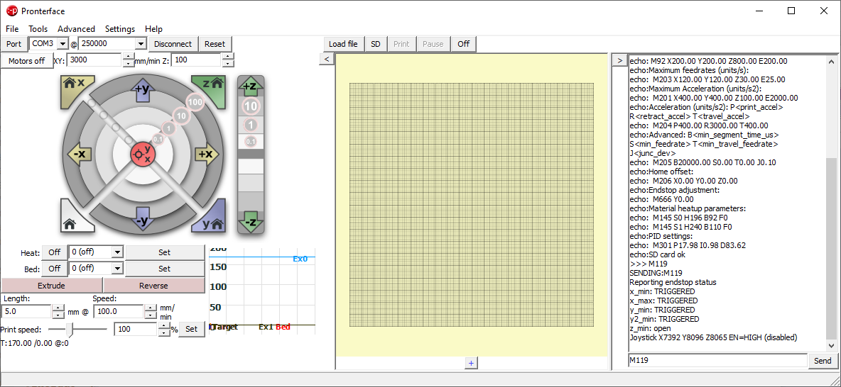
My question is about the m119 command response. All of my axis read “0” on min and “16368” on max. currently with the pre loaded settings my controls only work very close to the neutral position. If I change my values to the full throw (0-16368) will that send 5v to the signal pins and overload them? Or is there code that keeps it to 3.3v max?
I am using a relatively narrow range of about 5600 to 11000, which is about 34% to 66% of the full scale. These values describe how to interpret the input signal coming from the joystick and can’t overload anything. The narrower range reflects the narrower range of signals that my joystick generates. A different joystick can produce a wider range, in which case those values should be updated to reflect that range, which could be the full scale 0 to 16383.
If you need to keep the voltages within 3.3 then I am guessing you have one of the 32-bit ARM boards. In that case you need to provide 3.3V to the joystick positive connection, and then the output voltage from the joystick will always be between 0 and 3.3V. 0V should produce a reading of 0 and 3.3V should produce a reading of 16383 (or close). If you supply 5V to the joystick positive then the output could be above 3.3V and that could produce issues.
Thanks for the reply. I confused my current setup (Ramps 1.4) with research I was doing on making the change to a MKS SGen L (32bit) and that made me hesitate. I changed my values for the full 0-100% and it is working great! It really increases my workflow with just getting the router out of the way when setting up a job on a full endstop LowRider2. It also makes parking and un-parking in the cradle a quick task.
Just purchased the joystick. I think I will be using the MKS tft 32 boards with the wifi module instead of octopi. This setup really looks clean. I like it a lot.
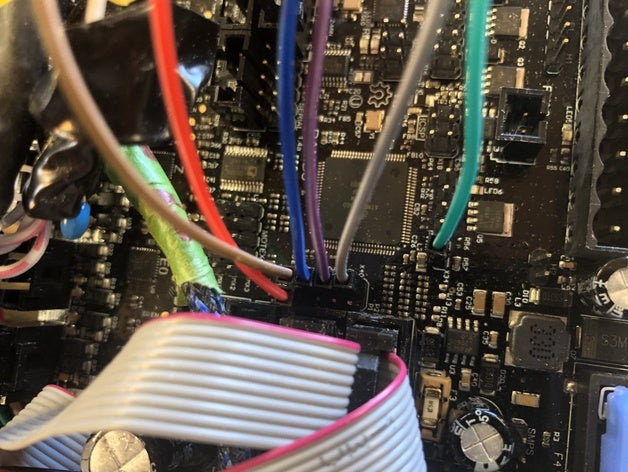
Yes this should work except the colors of the Z axis wires won’t work with red positive and black negative and white signal. In my setup I used red and black as positive and negative and other colors for x and y only (like your diagram).
But for Z, the wire should be white to positive, red to negative, and black is the output signal. I have a picture of mine here Joystick managed by Marlin
Ok the EN=HIGH (disabled) means that the enable pin (you had set to D42) is disconnected or is being driven high. You should have a switch between D42 and GND, and when the switch is closed, it will enable the joystick and when the switch is open it will disable the joystick. This is a safety measure so if the joystick becomes unplugged the tool won’t take off on you.
You could also comment out the line \\#define JOY_EN_PIN 42
and it would operate without the enable/disable (effectively always enabled) but I wouldn’t recommend this because it’s unsafe.