@gforce2010 - Reporting back on SKR PRO 1.2: IT WORKS.
There are some gotchas so ill try and give some basic steps:
- The diagram I used for wiring MY joystick is as follows:
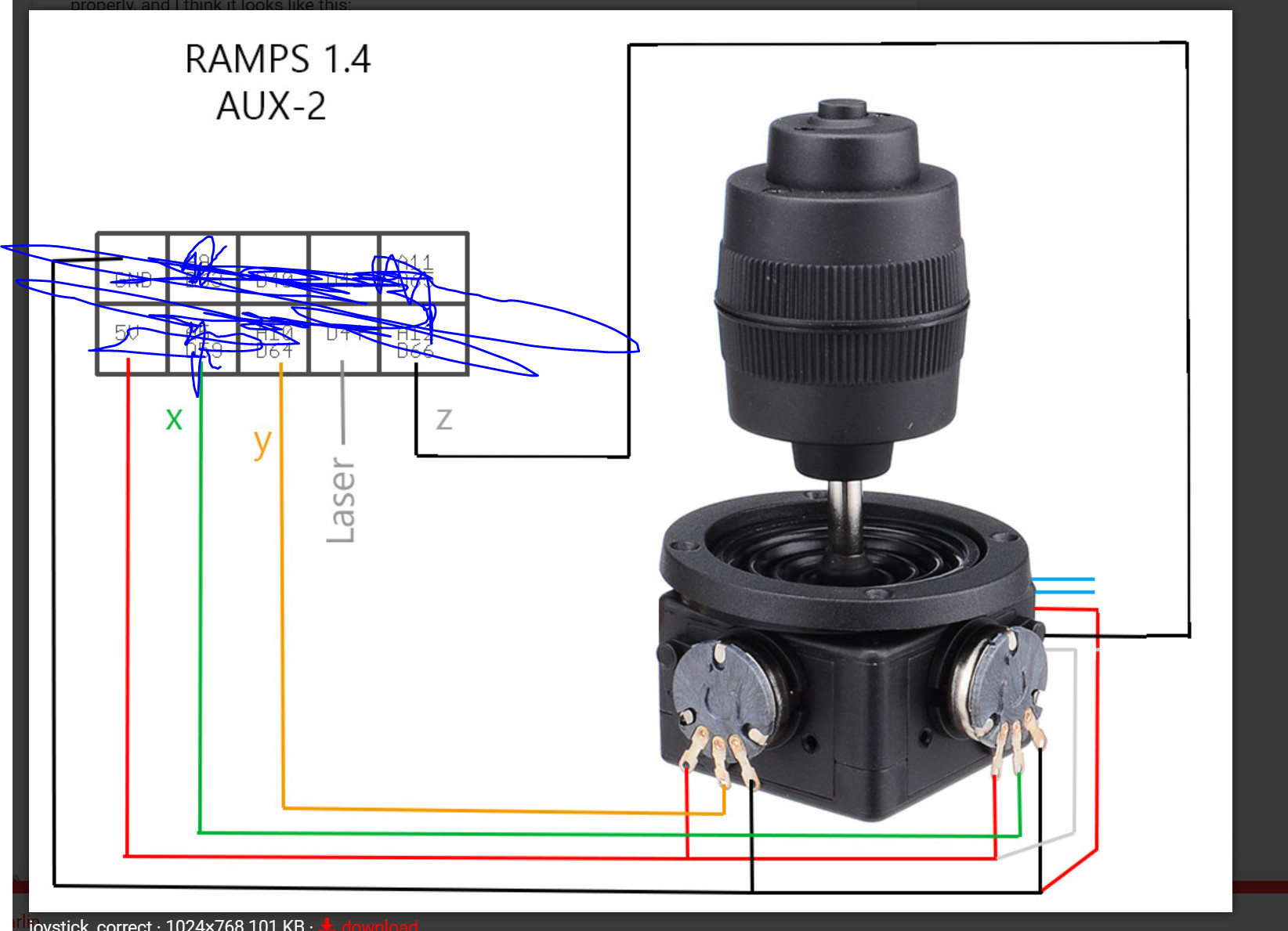
X: PF8
Y: PF10
Z: PF9
EN: PC4
HERES THE TRICK: You must use 3.3v output on the board near the endstop switches rather than using the 5v as much of this post describes.
configuration_adv.h:
#define JOYSTICK
#if ENABLED(JOYSTICK)
#define JOY_X_PIN PF8 // RAMPS: Suggested pin A5 on AUX2
#define JOY_Y_PIN PF10 // RAMPS: Suggested pin A10 on AUX2
#define JOY_Z_PIN PF9 // RAMPS: Suggested pin A12 on AUX2
#define JOY_EN_PIN PC4 // RAMPS: Suggested pin D44 on AUX2
//#define INVERT_JOY_X // Enable if X direction is reversed
//#define INVERT_JOY_Y // Enable if Y direction is reversed
//#define INVERT_JOY_Z // Enable if Z direction is reversed
// Use M119 with JOYSTICK_DEBUG to find reasonable values after connecting:
#define JOY_X_LIMITS { 0, 8000-400, 8190+400, 16384 } // min, deadzone start, deadzone end, max
#define JOY_Y_LIMITS { 0, 8000-400, 8250+400, 16384 }
#define JOY_Z_LIMITS { 0, 8000-400, 8080+400, 16384 }
#define JOYSTICK_DEBUG
#endif
Tuning the Joystick:
Once i got it all wired and plugged in. I attempted to “zero” the pots on the joystick as they are adjustable. I attempted to get the resting value to 8000 by unscrewing the adjuster and moving the pot manually. You can do this for Xand Y, but my joystick Z wasnt adjustable… luckily it was pretty close.
Once tuned, I pushed each axis to each side to get max and min. For me it was the whole darn range — thats ok.
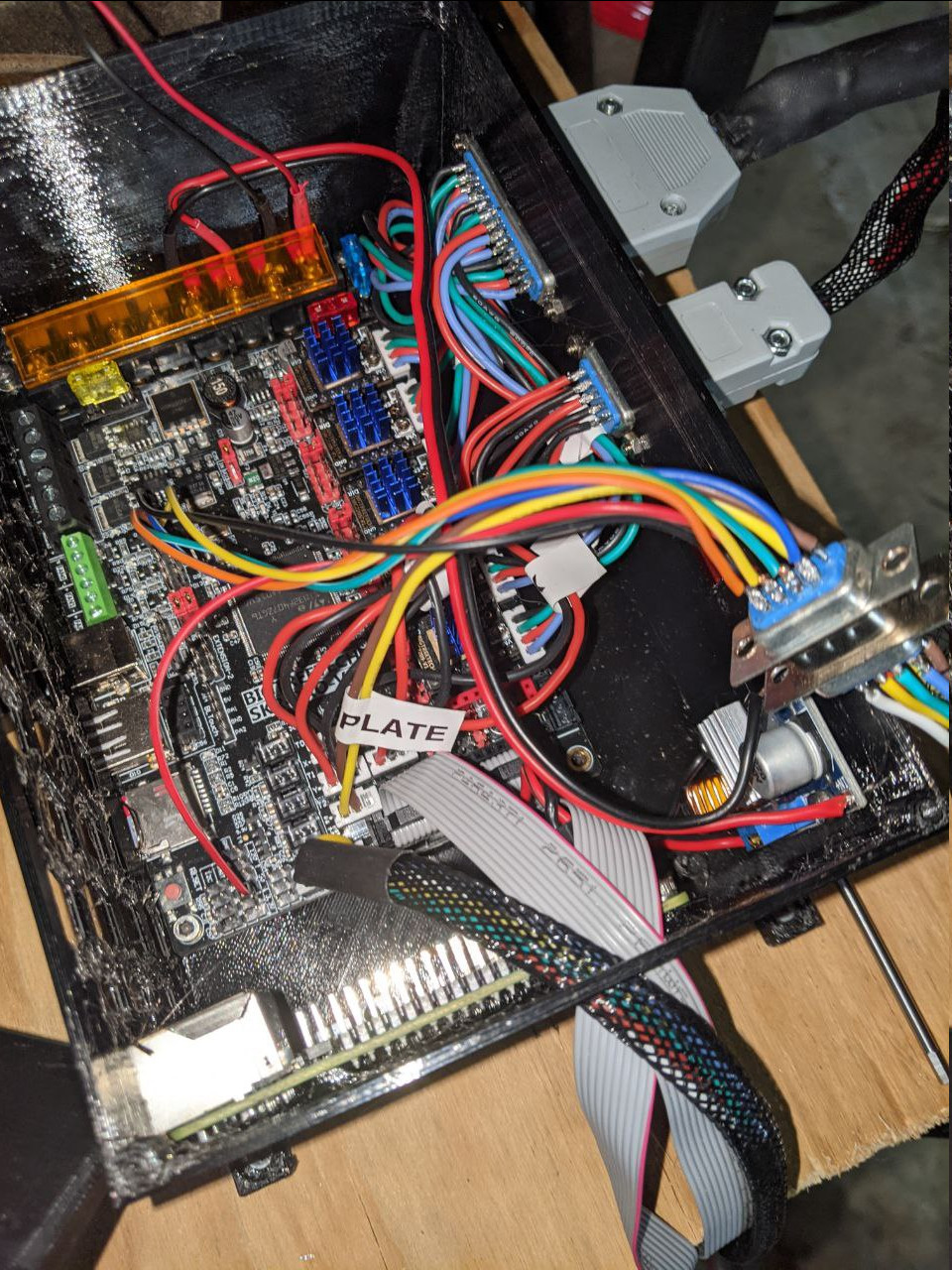
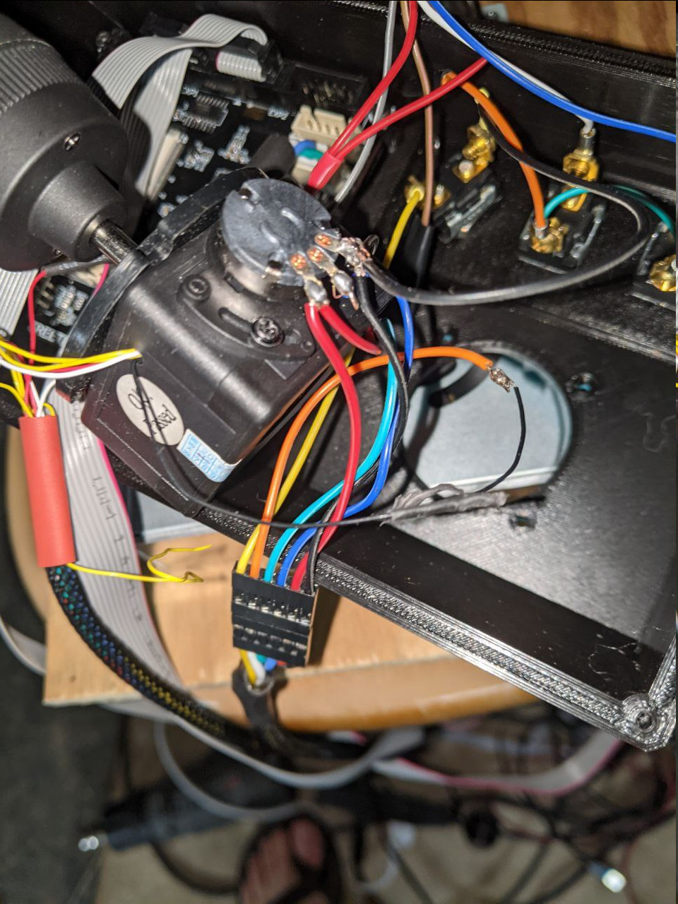
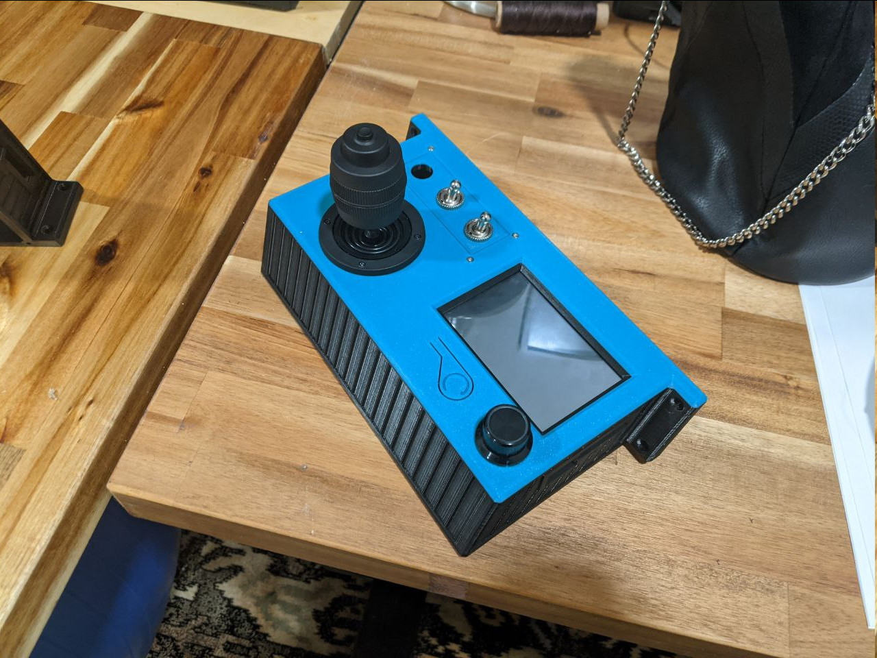
Heres some pics: