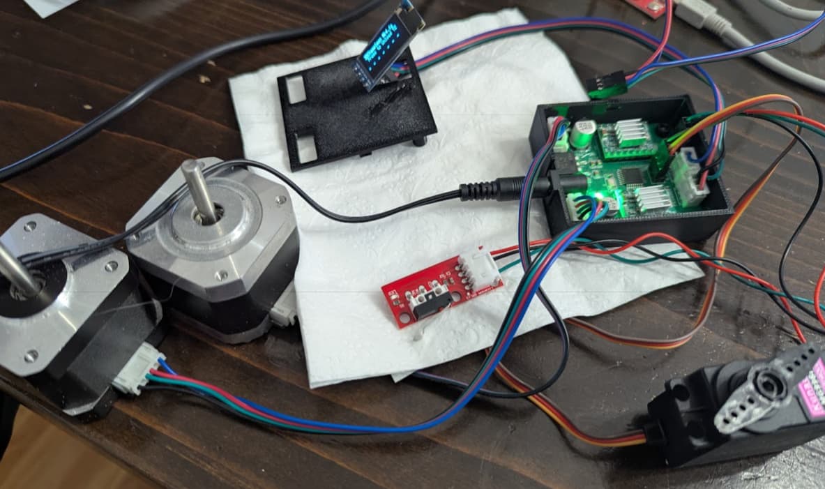
Had to pull this back a bit. The extra channels on the Octopus don’t do anything. the macros make the extruder run, but not the configured selector or filament loader/unloader, so retrofitted the motors with the 3dchameleon controller to try it out. wired the switch directly to the octopus IO pin and made some macro code:
[output_pin c3d_switch]
    #pin: PD14 # FAN4 not PD5 or PD6
    pin: PD6 #  serial rx pin over by the bl touch

[gcode_macro press_button]
description: this sets the state of the output button
gcode:
  SET_PIN PIN=c3d_switch VALUE=0  # pulls the pin low to "switch" ON

[gcode_macro release_button]
description: this releases the state of the output button
gcode:
  SET_PIN PIN=c3d_switch VALUE=1  # releases the switch low state to go back to pullup OFF

# initialize
[gcode_macro init_chameleon]
gcode:
  press_button  #call button press
  #gcode_pause 1.5
  G4 P300  # wait time for x ms to hold button down
  release_button #call button release
That looked pretty ok, but the wrong OLED display in the stash connected up wouldn’t read right… it was a 0.91 and was set up for a 0.96, so why not modify the code and fix it.
I didn’t set up the arduino uno as ISP correctly and now it needs to be ISP’d. Tried the nano to reprogram the uno and botched that, so it is on to the pico as an ISP to reprogram the nano that will reprogram the uno that can then reprogram the controller so the oled will work and the switch to control the color change will work directly from the octopus without the bed or core triggering it. What was that story about a mouse and a cookie. Some days I guess…
Today’s gains… a couple lines of code
Today’s loss… a whole bunch of arduino IDE time wasted.
No good excuse other than I’ve only used arduino as ISP one other time about 6 months ago and forgot how to do it.
ok, so i ordered a usb-asp programmer from amazon. It got here this morning. It revived the uno, the nano, and the chameleon board. Because it only works on my linux box, I’ve converted the uno to an ISP and it is now working (be sure to use the ctrl+shift + u or sketch->upload using programmer so the programming board doesn’t get written to). The oled change that was made didn’t work initially because the driver with the project doesn’t use the .display() command after changes, so it was showing garbage, but the button worked and the motors buzzed. The shortened button timing works as well. It was reduced 10x so the octopus doesn’t have to wait for 2400 ms, it waits for 240 ms.
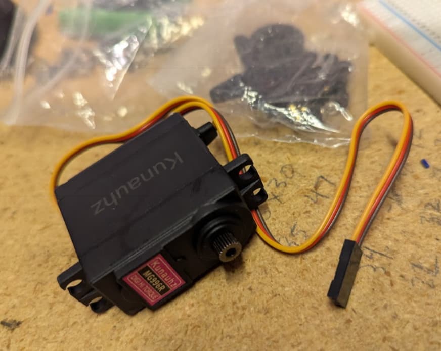
A servo arrived with the programmer, so I’ve been messing with the clippy function. The hardest part was finding where and how to plug it in. The servo for clipping the filament is a std size rc servo, not a small weak 9g one, like a 20 kg one ~$12 on amazon (pic below). It connects to the ICSP header on the power side, but the power and ground wires are separated by the signal, so the standard servo wiring is not going to work. Additionally, the power draw from the servo may require its own power supply, so the grounds would be tied together from the servo and the 3dchameleon board and the servo power supply. Teh power supply output + would to the the servo and the signal would go from the board to the servo. I’m hoping I got a 5V servo and I’ll see if it will cut with the base power source. If not, then it can be upgraded. The octopus board puts out 12V or the octopus power supply puts out 24V, so a buck could be used just for this device.
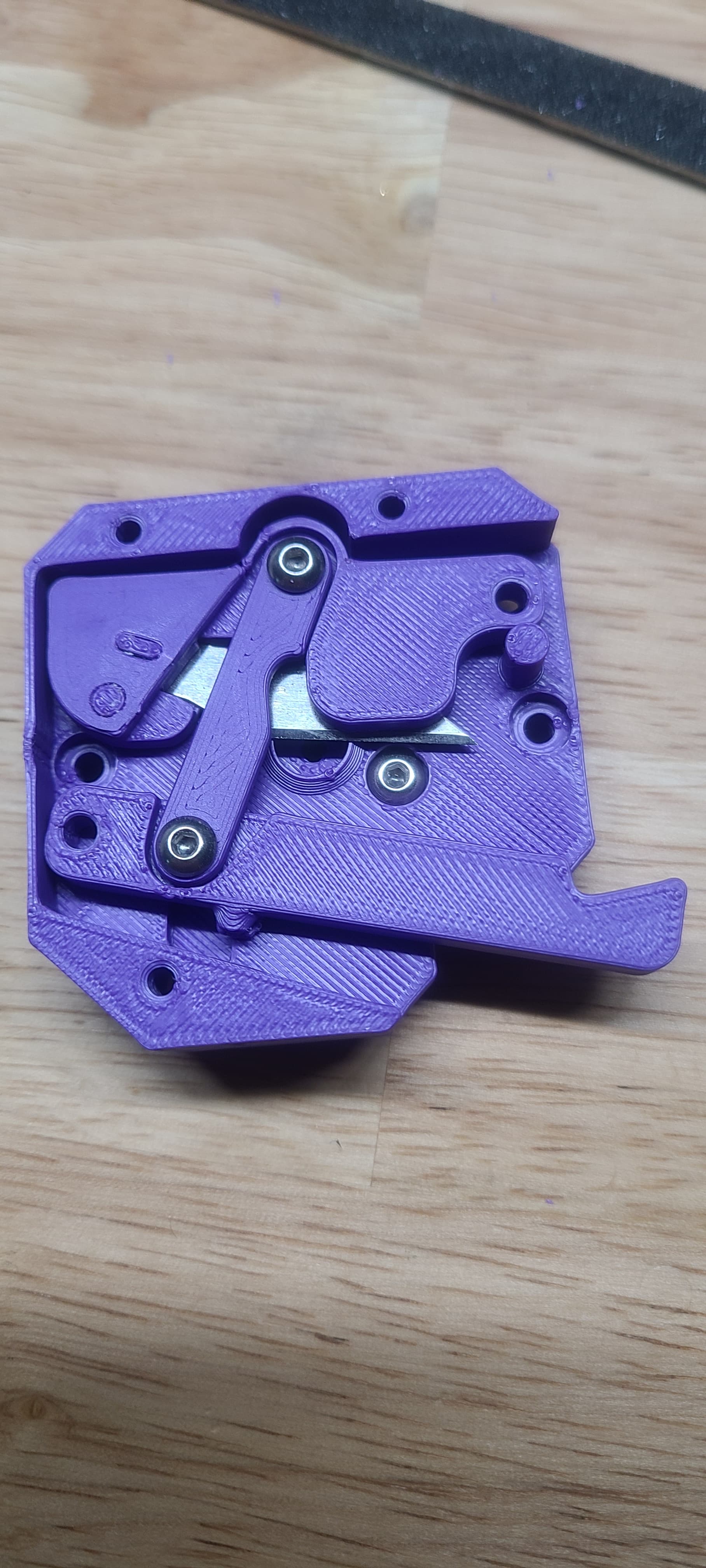
I’m not liking the single button interface. if the system power cycles, then what? It doesn’t remember what filament is in there and it cuts it when it restarts. It did load and print the 3dclipping shear through the filament 1 position. With the Y so far from the extruder, the rewind time is 17 seconds and it is a mess without a rewinder or filament buffer.
so it would be cool if there was a clean way to mount it to an H2V2s that wouldn’t kill the fan setup, the accelerometer mount, or kill its accelerations due to the mass of that metal-geared servo. Thinking of moving the filament sensor to the core, then putting the y right on top of it and festooning the 4 filament tubes overhead.
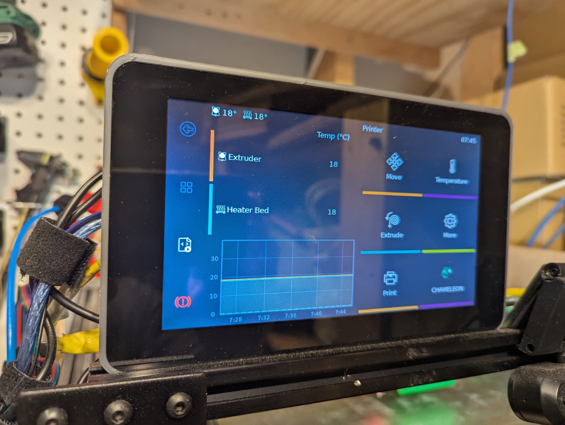
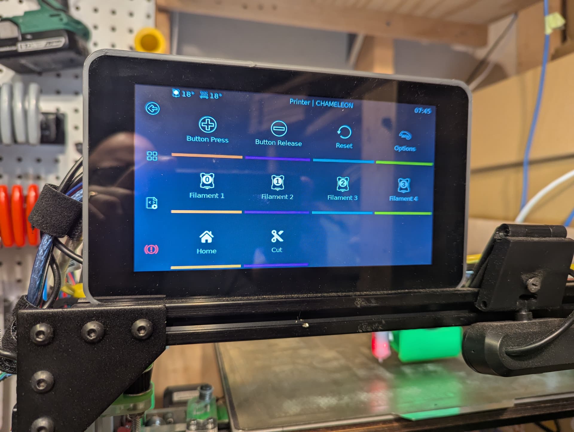
The good news is that the printer remains functional because after the chameleon homes, it doesn’t interfere with the main extruder’s ability to feed. I’ve been tinkering with the chameleon-klipper klipperscreen menu items and macros. If it turns into something useful, I’ll share.
Was wondering if anyone offloads klippy/shearer servo to the frame and rigs steel cable in a reverse Bowden style setup so servo can remotely shear filament near the direct extruder assembly. I haven’t thought about this much, so…
that is a good idea. but I’m probably not going to design that. I get analysis paralysis from thinking up mechanical assemblies… or software… or anything other than youtube shorts lately.
There is a 5 filament feeder Y on thingiverse you can print. I’m interested in seeing what you came up with.
I’m attempting to strip down the semi-automatic features in the 3dchameleon firmware so you can run it from the klipperscreen. I dislike the locked mode where you have to hold the button down for unload and then load in that order. the more I study it the more I understand, but we will see. Grand designs and not much time so not sure how far I’ll get.
looks like it would be cleaner to add the functionality and not remove what is there.
I’m going to add a cut function for 9 pulses, a channel activate function that will allow jogging of the filament. When the channel is active, a second and third pin will allow the extruder to move forward or reverse for jogging the filament in and out without requiring it to be cut, so you could preload the extruder for filament 4 when 1 is already loaded just to get it primed, etc. pulsing the primary button will then disengage the jog mode.
whenever I run the servo cutter, it kills mainsail and the web page refuses to load. klipperscreen works just fine, but only the touch screen interaction works. no ssh, no web page on wifi or wired connection. interesting…
I think it is a raspberry pi network issue and thinking back on it, it has been fairly reliable lately, but has had a history.
The servo is powered by the chameleon board. the chameleon board is IO connected to a few pins on the SKR (pins PD5, PD6, and PD14: mode select, load and unload pins). The SKR is powered by 24V and it is USB connected to the raspberry pi that is having the wifi / ethernet issues. THe Pi 3B has run both interfaces for the better part of the year serving klipper and an ssh server so remote machine access via ssh or web control with klipper mainsail is possible. During all this, the touch screen works fine and everything functions, just the network connection drops. The router thinks it has an excellent connection, but ping response is “unreachable” it could be a firewall “improvement” on my PC, but then it should ping from other devices on the network. I don’t know if there is a log on the pi for it… it may be time to put in the pi5 and retire the 3.
I’ll get spec info on the servo 5V 3A. The board supply is 12V, 1A, so i wired in a 5V 4A supply to the servo and tied in the grounds. It appears to work from the printer panel and the network is back up.
no cap for the spike, but the 5 V must have been coming from the rpi somehow. Its buck is supposed to be a 10A supply though, so that is fishy.
I like the servoless option from a mass standpoint. following that with interest.
You’ll have to show how you had this wired. rpi don’t have significant current source capabilites for peripherals. Did you wire both the servo and the Pi to a buck converter, or did you have the Pi powering the servo somehow?
the only connection to the pi was via usb to the controller. The controller had a pullu;p pin set to trigger low that was connected to the signal pin on the chameleon. I think this may have been a problem as well. The chameleon is wired with 5V, ground, and signal. they are designed to go into a switch where NC is signal and 5V connected. Then switched is signal and ground connected. I connected ground between the boards and an output pin from the octopus to the signal pin on the chameleon and it worked most of the time, but the chameleon was not consistent. I’ve since put a relay between them that the controller triggers and the original chameleon wiring gets switched as designed.
the servo was on the chameleon board 5V supply which is regulated down from a 12V input at 1 A.
I connected the grounds of a separate 5V 4A transformer from main power and the chameleon ground with the servo ground connected to the 5V also. the 5V goes to the servo and the signal goes from the board to the servo. It works well now. No more issues.
Roger that. I was planning to use them in one of the Sterilite totes with a seal in the lid. Drew up a base in CAD that I printed in 4 parts so I could put a good amount of desiccant on the bottom of the tote and then set those on top. But I know everyone does their filament boxes a little different so not everything will work. Hopefully you can come up with a good solution without too much hassle.
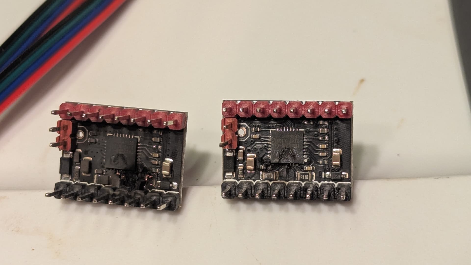
Printer has been intermittently losing a z motor connection and fails to bring the bed up when homing. Opening the wire tray and moving the fan over the motor drivers to see if i could get a better look then powered it on…
It first blew the extruder driver. I removed that and secured everything and then it blew the z driver, so clearly something is not happy The issue appears to be some of the early crimp connections made when putting in the test z brake board, but the 24v power supply has been struggling. Lacking the motivation and time currently to fix it, I just can’t not share the smoke evidence. Smh. #facepalm. I’ll video the next power in just for fun.