Wow, nice looking dust shoe skirt and bristles. I may reprint mine to get the newer file to not have the bigger gap in the bristles.
If yours didn’t stretch to close, it really is not a big deal, but you can scale the print only along the long axis and get whatever size you want.
By the way, I don’t see a need to insert the bristles both ways. If it gets a little bit stuck, a tiny drop of grease in the track and it slides very easily. No mess.
Yeah, if you don’t insert them wrong side in like I did, they are easy.
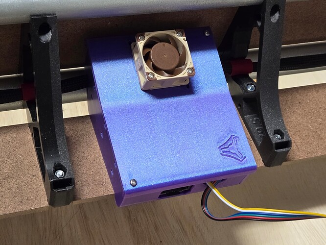
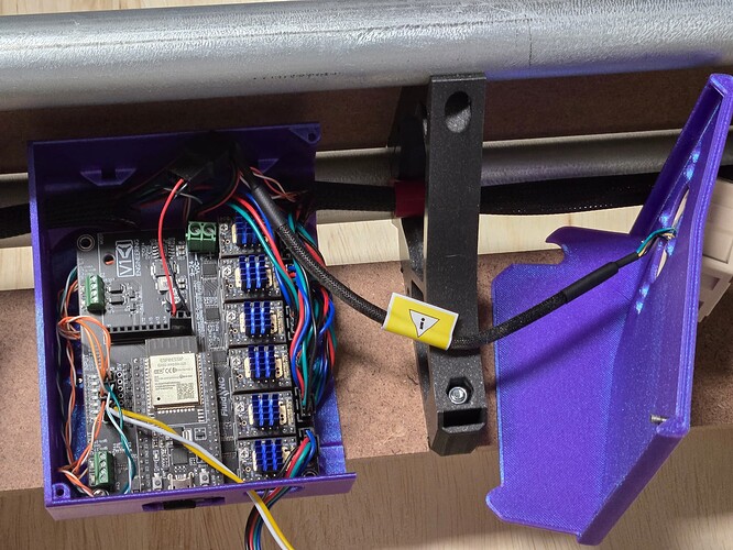
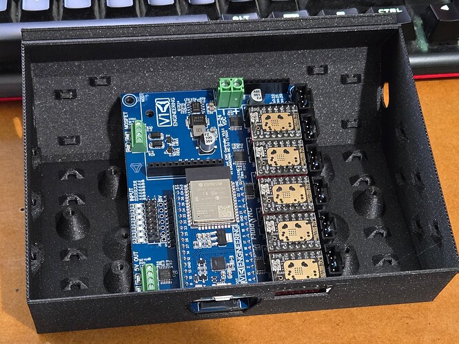
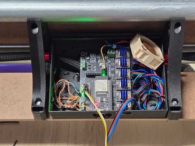
I installed Ryan’s Jackpot case and tidied up the wires somewhat and I made some observations for things that I might prefer for my use case.
Some of my wires have extra length and it’s cramped. The side holes are too small for my X wires and I am reluctant to punch holes in the lid. There are no tie downs for the extra wire so it wants to escape when I’m closing the lid. The endstop indicators are not visible (not a big deal).
Small things generally.
I have extra room between the braces so why not use that space, and add some features while I’m at it.
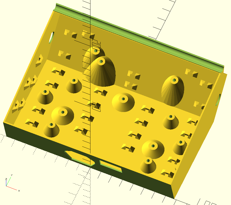
This started with very much the same spirit as the Jackpot case, and I went crazy with little zip-tie features:
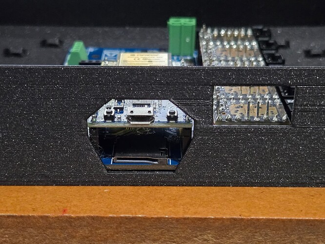
Extra length can get tucked away in any of several places. The opening for the ESP32 and fans is effectively the same. One of the goals is to allow a modular lid (not done) that could be multiple pieces. The idea is for a hinge but it may just end up being a clip-on, if the hinge doesn’t work well.
Having multiple pieces will make it easier to handle the fan wire as one example. The fan wire could be short, and it could be plugged in after the fan portion of the lid is closed, for example. It also allows experimenting with different options and features without redoing the whole thing every time.
A multi-part segmented lid also allows for an opening so the X wire or 4th axis can exit through the lid, without having to replace the entire lid, and the hole can be small (smaller than the connector) if it is on the boundary between lid segments. When not using the 4th axis, the lid segment can be replaced with a segment with no hole.
I also included extra posts, three to the left and three to the right, for possibly mounting extra stuff, like a buck converter or a physical relay or whatever.
Also the left, right, and front edges are all straight and co-planar, which would allow for an acrylic lid that offers visibility to the endstop status.
And one small touch, the holes in the side align with the braces. I have little clips that hold the wires along the bottom inside of the braces, so these will line up nicely.
All those zip-tie anchors are pretty ridiculous. The wires will be secure like never before!
Now I just need to do the lid.
I have made it a little bigger now that the SKR box is done and we have larger spacing on the strut plate, but not as much as you. I have all my extra wire outside the box to keep it uncluttered as possible.
You have it flat and not hanging off the edge, with a lid on how much room do you have above the heatsinks?
Why do we try and make the case so small? Like other than some extra plastic, who cares if it was 2x the size?
Just seems like we are making it compact for no reason when there is plenty of room between the struts and nothing really else to put there.
I have to ship them.
Fill the case with hardware or other parts?
It is never empty.
It is just not in my blood to make things big. I got all my wires in there as is comfortably and bundled the excess outside the box and felt like there was plenty of room (in the jackpot box), since the release I then added some more room after we figured out how big the SKR box was.
I know it doesn’t seem like much but lay out every single part, then think about fitting them all in a specific box and shipping it across the globe internationally. If every single part is 1mm bigger we add a substantial amount of plastic and volume. I have to use flat rate boxes or shipping doubles I can’t just get a bigger box.
Fair enough and would take you longer to print.
Understandable.
I think for a base release it is fine.
There are applications that will drive other solutions.
For example, I have a stack up of two expansion boards- one of my custom proto boards with a pendant interface.
That expansion board in turn has a stackable header which you can then install a 2nd expansion board on (the isolated RS-485 spindle module.).
So, in total a double-high stackup of expansion boards.
That, plus all the assoicated wiring, won’t fit the stock case, so it’ll get a remix or alternate enclosure. Anyone intending to use such a setup will know going in that they need a slightly different enclosure. That’s all good, and doesn’t need to drive the simple design to be stupidly oversize.
I do agree with others that the stock one seems a tad too tight, and I am missing having the tie wrap provisions.
In a funny twist, I have been fiddling with it in OpenScad and have not quite made a revision to match Jamie’s version. I was 80% of the way to something that would look pretty darned similar (except with provisions for a double stack of expansion boards and ducted 5015 fan exhaust over the steppers.)
I have them on two sides, that let me secure all my wires pretty easily.
The more cases out there the better!! I have what I will ship and then DIYers can choose whatever floats their boat.
Would be cool if there was an open scad version where you could make it the exact width between your braces.
Yes, I have it flush with the edge (assuming 5.5 mm wings on the bottom strut plate) not hanging off the edge. As a consequence, it needs two extra clearance holes in the strut plate for two of the Jackpot screws (unless you use short ones).
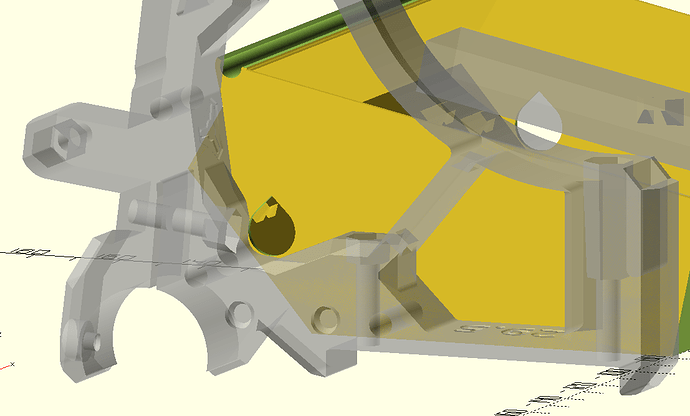
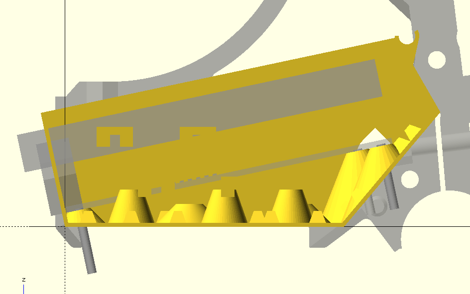
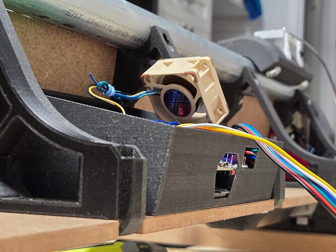
This is the profile view. The upper rectangle is the zone for the heatsinks and there is a bit of room above it.
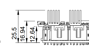
The heatsink zone starts 14.5 mm above the bottom of the PCB and extends 11.5 mm above that, for a total height of 26 mm to the top of the heatsinks, which is derived from this:
The lid has a bit of room above that, as shown. I don’t have an exact number for that clearance.
Yes! Some of the zip-tie locations are hard-coded at the moment and not size dependent but for a reasonable range of sizes it could be parametric.
It was supposed to be a prototype but it fits well, so it might be permanent.
The extra room is a minimal benefit, but I like it anyway. And all the wires (except X motor and endstop) sit neatly below the plane.
I still need a lid.
Those are the “old” braces, right? The newer ones being higher would make it fit even better optically. ![]()
Yes, this one is RC2 with helicopter Z endstops. I’m also building an RC3 with the same X size.
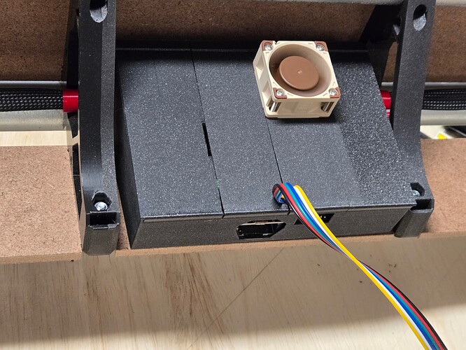
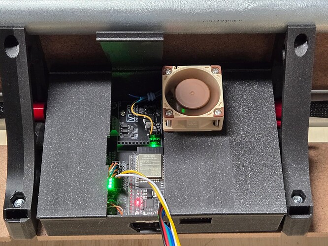
Ok here are the covers:
And this illustrates the modular lid.
I can plug in the fan after the right segment is closed, so the fan wire is short and neat.
The fan wire is not exactly earth shattering, but the broader modifiability is the point.
The key here is that Ryan’s shop is the nominal way for most people to get to a working machine. The instructuons, the test crown, the firmware and printed parts are all that “yellow brick road” through the scary forrest of CNC machines. If someone wants to venture off and make a bigger box, go for it. But what we’re testing here (and getting good feedback that I hope Ryan is reading) is wether the box is big enough for that nominal use case.
Ryan also has a lot of good reasons to use zip ties for belts. But it turns out a lot of people didn’t like that. Ryan eventually went away from zip ties and I haven’t heard as many complaints.
I can imagine Ryan thinking about packing these boxes for the next 2 years and thinking about the trouble a bigger box would cause. Ultimately, Ryan knows best. He is the only one of us that packs boxes.
