Hey what is your thinking with the Z trigger? I am looking at mine and I am not sure what to do here. The trigger point for the roller versus non rollers have a different trigger point by a mm or two.
The more subtle the trigger angle, the more accurate the trigger point…if we move slow enough.
If it is just a single bump I feel like that is a steep trigger point and not as accurate, less so than the flat spot we used to have on the LR3.
But I can sort of convince myself of the other way as well.
I think we disagree on whether steep or shallow is more accurate. I am basically in agreement with @jono035 here:
I have made my case and I don’t want to keep harping on it. But if I can somehow test it, then I can bring evidence or I can learn something. This part has both shallow and steep available.
Also I have been using soft stops on fluidnc so I can jog with reckless abandon, and with soft stops enabled you can’t move past the endstops. Maybe I will disable soft stops for Z.
I really am not sure which way is better now. Either way more room is needed, the easy solution is flip the endstop over that buys all sorts of room but has the arm up in the position to catch chips and dust. Moving it to the top seems super wonky.
Pulling the arms off the endstops would be great but I feel like they would wear out the little plastic nubs pretty fast against rough aluminum edges. A little harder to adjust but not that hard.
Proximity sensors are sorta big, definitely expensive and take three leads.
Any off the wall ideas?
We need to gain 8mm, is the big one, and it would be nice to use the endstops people already have that they got from V1.
put it inside the z screw channel and trigger off the screw? (probably not)
trigger on the back side off the strut brace… call it a min brace and have it hook around the XZ plate to catch the endstop? that would put the endstop on the back side.
use an IR prox sensor with a reflected beam to sense the xz plate and then have it trigger when the plate is high enough to not reflect anymore
use a beam break IR sensor like the diy encoders and have a flag in the lower tube trigger it when it gets to the right height.
all ir sensors would be behind the xz plate and out of the direct path of flying debris
just spitballing here - feel free to ignore
Well, you went all crooked on the plate, what if you rotate the endstop holder? E.g. you can control the angle of the protrding lever/roller. So have mounts with two different clock angles.
Likewise… Try 3D… Is there a small angle you can tilt endstops about Y axis to prevent chips collecting, but still function without binding or new off axis issues?
The screw travels above the yz plate.
The strut could hold one of the larger proximity sensors…
90 degrees would mean the lever arm would need to face up.
I thought about having it always triggered on the XZ plate and when it is at the top it would untrigger falling off the bottom of the XZ plate as it moves up.
So basically using a NO switch but reversing the lever action so that it’s normally triggered, and you take the reset action as a trigger?
This will require the XZ plate to be at least the Z range in height at the switch location, and does make changing the trigger height unadjustable, but I don’t think that is nearly the problem that it was. Marlin, FluidNC, RRF all have auto-square capabilities, so the software adjustment is easy enough, and gou can use a bottom surface so noplace to accumulate chips.
I can just see builders using the wrong switch terminals though. C and NC are the outside 2, so polarity doesn’t matter (though I make them the same anyway.) C and NO are edge and center, but it won’t work if people connect NO and NC instead. Those 2 should never short to each other, therefore always be in triggered state.
Aside from that, the solution seems to me to be quite elegant.
I also measured repeatability on the shallow face, and the results were so-so, not to 0.01 mm. (Z has 200 steps per mm so 0.005 is the theoretical best, 0.01 would still be great.)
Here is the methodology:
Make sure pulloff_mm is the same for both Z motors. In my case 4.0 mm.
Home Z. I reduced the homing speed to 30 mm/s for this test (excruciating), just in case.
After homing, move up by the pulloff distance. This is the point where theoretically both endstops should trigger.
Reset Z work coordinates to zero using G92 or the button on the FluidNC UI.
This moves down 4mm, then back up 3.95 mm, and then moves in 0.1 mm increments once per second. You have to listen closely and you can hear each movement and count them. Watch the LEDs and listen for the endstop clicks. Then run it again and again (do not reset G92 between runs).
Ideally, the endstop clicks would always occur on the 6th, or 7th movement if the true endstop threshold were between -0.01 and 0.0 or between 0.0 and 0.01.
My results showed sometimes good repetition from consecutive probes, but sometimes it would shift 0.3 or more.
Anyway as for a better solution, I’ll have to think about that some more…
How about you flip the Endstop over but make the holder‘s edge match the edge of the plates to be parallel. Then only the little nub looks out and the arm part is covered by the holder. This is jus a very bad napkin sketch, but you get the idea, I guess. (I had the roller Endstop on the beta flipped, with a good dust shoe there shouldn‘t be too much of a problem with debris that way if the lever is partially hidden).
For what it’s worth, the 3.8.2 release of FluidNC now includes flow control (looping structures) in gcode. It’d be a natural to set up a looping test like the one you show above.
I looked at that, actually, and other stuff about variables but I could find no way to condition or even print out the endstop state. On Marlin I could do M119 and capture a giant text file and post-process it, but with FluidNC I know of no way to detect the homing endstop state other than manually looking at the status and manually listening for the motor movements, which is terrible.
Maybe one of the homing endstops could be connected to the probe pins in addition to homing pins, and some automated routine could do something with that, at least printing out the location for statistics gathering.
Before we get to the demo, here is how it is tested.
As before, I move near the trigger point and then step to confirm that it triggers at the right time, but instead of taking 10 steps of 0.01 mm increment to find the trigger location, I test accuracy of +/- 0.01 directly.
I move to -0.01, pause, and then move to +0.01, and if it triggers between these two points, then the accuracy is within +/- 0.01, which it does 100% of the time.
I have pulloff_mm at 0.5 mm, so after homing, jog 0.5 to move back to nominal trigger point, then G92 Z0, and then run this gcode for testing:
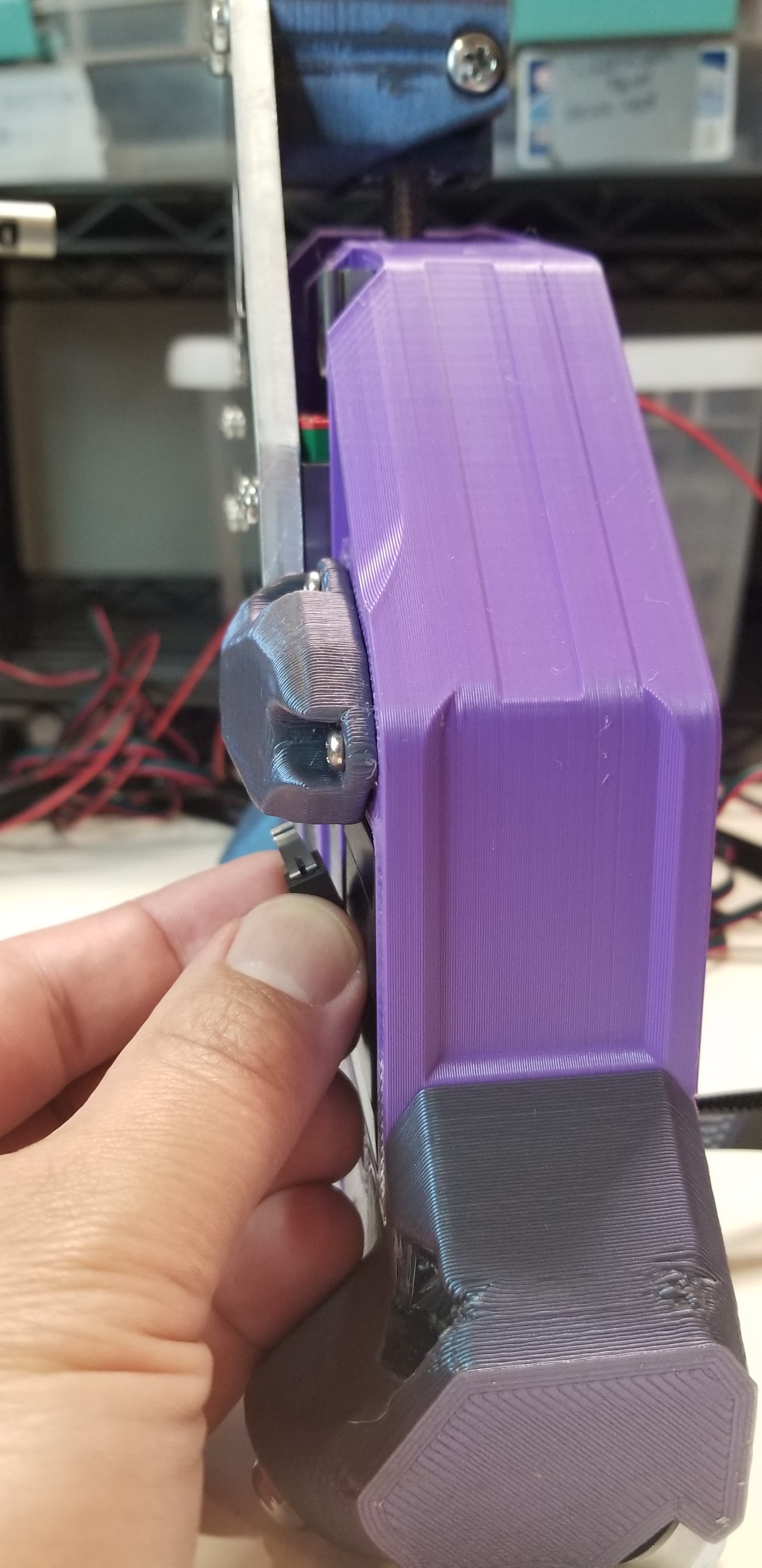
This is a big one: it doesn’t really fit! The endstop with plugs and wires and everything is maybe 25 mm long, and I cheated here by soldering and bending the tabs to get it to fit in a tight space.
It requires a longer lead screw
Homing speed should probably be slower. You can’t overrun the endstop by much at all, or it crashes and probably breaks. I am using homing seek of 100 mm/s and homing feed of 30 mm/s. I haven’t tried faster.
Kinda ugly (I’m sure it could be made cleaner)
Won’t work with 1-start or (probably) 2-start leadscrews. Limited to only 4-start leadscrews
Now the advantages:
Funny! Cool!
Accuracy, repeatability.
YZ plate is cleaner, less wire routing through channels
Easy to adjust in small increments for physical leveling. Software offsets not necessary.
Naturally scales with Z. Longer rails and longer Z leadscrew is all that’s needed to accommodate different sizes.
Switch surface is (still) vertical and won’t collect dirt
As I said before, it is not necessarily a fully-baked, ideal solution, but you asked for off the wall ideas and this definitely qualifies. And it does have some good properties.
I am still chuckling to myself. I think this is hilarious.
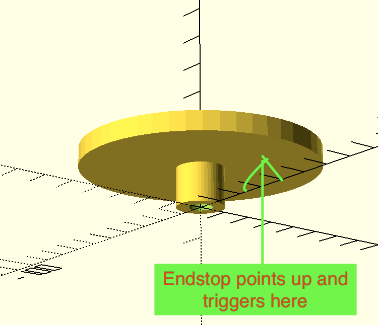
Couldn’t you also mount a circle collar at the appropriate place on the lead screw, and point the endstop UP to intersect that? Still mounting the endstop on the Z stub- just pointing trigger UP.
Edit: The top of the leadscrew would get a flange/collar that would look something like this:
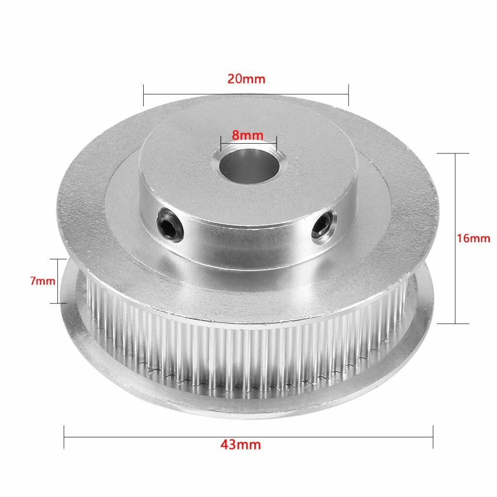
Edit 3- or instead of a timing pulley, use a handwheel. With either of these, you have a manual way to move the gantry up/down when you’re doing the manual assembly tasks.
It would probably tend to sweep the endstop clean, so if a wood chip lands on the little lever it won’t stay, so probably not a big deal that the endstop is facing upward.
You don’t get the amplification factor of the helicopter, but getting it to fit in the space is much more doable.
OMG, that could easily work! Flip the endstop over to move the trigger point closer and I think the geometry would work on most lead screws. You are a mad man. I need to think about this one