After upgrading my LR3 to LR4, I finally got around to properly installing my addressable RBG’s. I ran into a couple hiccups along the way which I just wanted to bring up to hopefully help anyone else trying to accomplish this.
I am using 5V from the Jackpot board to power the Wemos D1 Mini, and using 24V LEDs which are powered off the same supply as the Jackpot board. They technically should have a common ground, however I still seemed to be getting a flickering light issue. This was solved by soldering a wire to the Wemos D1 ground pad, and connecting it to the main power supply ground right next to the LED ground. After this I had full control of the lights through WLED.
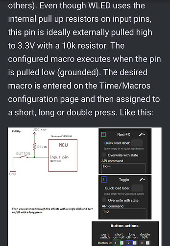
The next challenge was to get the Jackpot to control the WLED board. At first I played around with the button config on WLED and the button press timings in the macros Ryan wrote above, but that did not seem to have any effect. After further reading through the WLED instructions for push buttons, it seems that it expects this button pin to be pulled high to 3.3V through a 10K Ohm resistor. Then when the pin is pulled low it registers as a button press.

I wrapped a 10K ohm resistor in heat shrink and left the two wire ends exposed. I then soldered one of the exposed ends to the “3V3” pad and the other to the same data pad (GPIO 0 in my case) that the button wire is connected to. I was then able to change to any of 3 lighting presets on command through the Jackpot via the macro buttons. I set the macros to correspond to “Standby”, “Job in Progress”, and “Job Complete” lighting presets. Next step will be to add the macro lines to my start and end G-Code to change the lights to whichever job state the machine is in at the time.