I have an issue where if I connect to the ESP32’s USB and open the COM port I see the device is in the bootloader not running the FluidNC app. This of course is preventing me from using Universal Gcode Sender via USB.
I have done a bit of debugging:
If I remove the ESP32 board from the Jackpot board it works fine. When I connect to the USB I can correctly connect to the FluidNC’s serial port. So this indicates ESP32 is flashed and working correctly.
If I plug back in the the ESP32 to the Jackpot while usb is still connected to the computer it still works.
I took a look at the schematics and it looks like the Boot pin GPIO_0 is connected to GPIO_4 via a 1k resistor, and to “ST_UART” net. This net is low normally. I believe this explains why the ESP32 is going into the bootloader.
Has anyone else ran into this issue?
Can the designer(s) comment on why the Boot pin is connected in this way?
USB micro B.
More debugging. I just soldered in a 1k ohm pull up from 3v3 to GPIO_0. This seems to have solved the issue. I also just scoped the GPIO_0 and it looks like the UART data is still clean goes from 3v3 to 0v with clean edges.
I think this solves the problem for me…
Maybe the designer needs to look into this.
@The_Digital_1 - would you mind sharing the scope shots of the GPIO_0 on your fixed board?
If you’re feeling really ambitious and are good at soldering, could you pull your added pullup, and get a “before” scope shot?
Could there have been a change in the TMC 2209s? A lot or batch produced that has worse than previous behavior on the UART interface? Maybe counterfeits entering the supply chain? Such a curious problem.
(No pull up scope shot attached.)
OK so the scope just revealed another clue.
The GPIO is nicely sitting high at 3.3v even without the pull up. I can hit the reset button and its still at 3v3. It’s not until I actively open the com port, does it go down to 0.43v. With the 1k PU to 3v3. It comes up to 2.9V in that case where the com port is opened.
Another clue. There seems to be some interaction with RTS and DTR. If i use realterm app where i can set and clear those. I can cause or clear repro. However those settings are not available in Universal Gcode Sender as far as i can tell.
With ESP32 unplugged from Jackpot:
No repro (Boot pin high) RTS =1, DTR =1
No repro (Boot pin high) RTS =0, DTR =0
Boot low, board held in reset RTS =1, DTR =0
Repro (Boot pin low) RTS =0, DTR =1
I believe that is all normal and to be expected. That’s how flashing tools reset and put the ESP32 into bootloader mode.
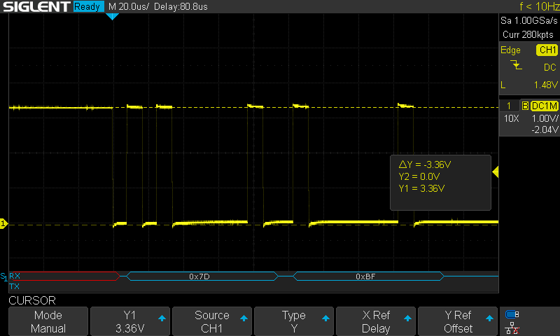
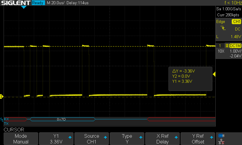
Here is where it gets weird though. With the ESP32 plugged into the Jackpot board: Repro (Boot pin low) RTS =1, DTR =1
No repro (Boot pin high) RTS =0, DTR =0
Boot low, board held in reset RTS =1, DTR =0
Repro (Boot pin low) RTS =0, DTR =1
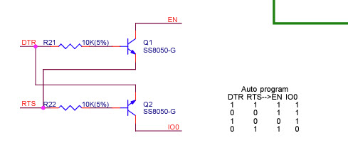
I did some more digging. Yeah if you look at the dev it schematic for the ESP32. You see DTR&RTS=1, and DTR&RTS=0 should both result in EN & IO0 = 1.
However what happens on the Jackpot board is because IO0 is loaded down with IO4, and the “ST_UART” net. The IO0 falls under the threshold to be considered high, and the device goes into bootloader when reset.
Funny enough this does not happen when RTS =0, DTR =0. This can be explained because keep in mind RTS or DTR when set e.g =1, that actually sets the DTR or RTS line low respectively. i.e. its active low. Thus when RTS and DTR are “cleared” i.e. =0 their actual nets are high. So what happens on the Jackpot board is when IO_0 starts to fall lower than threshold of Q2 BJT, the BJT starts to turn on which pulls the IO0 net up never allowing it to fall below the “Boot” threshold for the ESP32.
Anyways… that’s just my analysis. Let me know if you think this is wrong.
Ultimately IO_0 probably should not be used for UART TX. However if you needed to use every single IO… I get it, in which case, there probably needs to be a strong pull up to 3v3 on IO_0.
The diagram you printed is not actually complete, as shown it is not possible to get a situation where both RTS and DTR nets are both low, what is not shown is a capacitor and resistor network that introduces a time constant to the switching allowing for the correct sequence to signal the uP to enter bootloader mode. see usb - ESP32 Dev Board DTR/RTS - Electrical Engineering Stack Exchange
The DTR/RTS interaction has historically been a problem for CLONE boards manifesting itself in having to manually control RTS and DTS to force bootloader mode. It was never a problem (AFAIK) for genuine espressif boards.
The DTS/RTS interaction only happens at the instant of power up (or very close to it)… why is there comms over the UART at that time? Perhaps the easiest ‘cure’ would be to delay comms for a second or two.
Even as discussed above, that’'s not the complete story.
The jackpot places a funky series resistor between BOOT0 and the TMC2209 UARTs.
I suspect this is a kludge put there because of this very problem.
That didn’t make sense to me, but I suspect what’s happening is that when the TMCs aren’t enabled, the UARTS are actually sinking current, which is also pulling down the BOOT0 line.
I suspect this is also why boards with lots of TMCs are now using a mux because at some point even if everything else is OK, this effect of the TMC UARTs ultimately prevents booting most of the time.
Also, when the TMCs are first powered up they have a burst of their own serial comm, which also impacts the state of things and does appear to be a factor in whether the ESP32 boots or not.
I’m not sure all of this interaction is understood completely, and there seems to be a lot of variables at play, including the ESP32 and ESP32 dev board (genuine vs clone), and possibly some variation in the TMCs as well.
I like that series resistor less and less the more I contemplate why it’s there.
Interestingly, Ryan noted in the other thread that Bart’s other board designs are using GPIO16 instead for the UART comms.
I think thee double-use BOOT0 GPIO is potentially a bad choice for anything that has to do serial com at or near boot time because that’s when BOOT0 is doing its boot arbitration. If you use BOOT0 for some secondary task post power on, it needs to be something that is never active when the ESP32 is being powered up, reset, or expected to be put into bootloader mode.
Maybe it is as simple as an additional pullup on the jackpot board. I’ll hope that makes for a usable fix for all cases.
Thanks, @The_Digital_1 for some good scope shot and analysis.
I live in that world myself. One of my colleagues does orbital mechanics math in his head, iteratively, as we test things. I need a bunch of computers to keep up.
Yeah, but is it proper N-Body orbital mechanics, or does he fudge it down to 1 or 2-body orbital mechanics? Not that it’s any less impressive; I spent more than a few months tearing my hair out working out Hohmann transfers and managing the vis-viva equation in Kerbal Space Program, and that’s all 1-body mechanics (and I still ended up lifting most of my code from others).
Anything could be possible at this point but BTT is a pretty reputable supplier. When the Genuine esp’s get here I have a lot of testing to do.
We are finding the esp’s to vary with how they are made. The USBC version seem to have bad capacitor value to make booting weird. And most of the Micro versions I have to need a pullup for the rest to work as intended, this has not to this point effected anything but the web installer. You seem to have an odd ESP.
I do want to dig in further, but with these random issues we can either find a band aid for all boards (janky that doesn’t mess with a genuine) or just switch to genuine’s. Heck maybe there is a design fault in the jackpot? I can move these IO off these two pins but these two pins would still need to be used, and it would make the config files a bummer since the pins would change.
I’m listening…
Bart is adding an enable delay for the steppers in the firmware right now this might just help?
I would love some more testing or help in testing next week to make a decision.