Hello there. Almost all 3D printer, and most small CNC controllers here use similar 4-pin headers.
But, before going further, note that this reply is at the bottom of a 20 day old thread, so many readers may miss it as it’s an old thread.
I’m curious if this is a next set of steps for the project you described below:
That’s a very interesting project and I hoope you paste more about it as you proceed.
In the picture above, you have quite a collection of cables!
I see the geared stepper motors appear to have a 6 pin style connector with 4 contacts populated, and then these two geared motor harnesses join into an 8 pin ribbon cable. Is that correct?
That configuration is extremely rare in my country, in fact it is the first time I’ve ever seen steppers paired and sharing wiring run that way.
It looks like you were then able to split the 8 wire ribbon cables out into sub bundles to route to the jackpot. That must have been a lot of work for you.
Hopefully you were able to sort out A and B coil pair mapping, which would be the next hassle if they are mismatched.
As mentioned above, most folks here do not use the locking style 4-contact connectors because we prefer the option to flip the stepper wiring over in case the stepper is moving opposite our expectations.
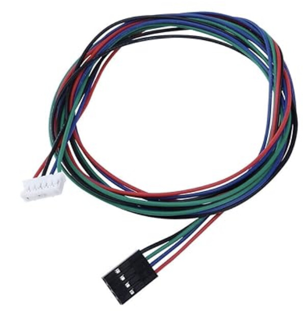
I have seen cables that map the 6 contact style stepper back to a 4 contact plug, but because those are relatively rare I don’t use them. As an example of ready-made cables of this type see the link below.
NOTE: I have not used the stepper style you show above. The link is only to show an option that might be better suited to you in the future- if you verify it correctly matches your stepper pinouts.
EDIT: Inserted a picture from the above link since it didn’t render here.
I completely understand the value of time. I have a couple of suggestions that might help that in the future:
-
Ask here in the forum before.buying things, especially now that we understand that your supply chain options are very different than those we have here.
-
It’s probably better to start a new topic than to jump into the tail of an existing one. I skipped over this topic several times since you’ve posted above because I recognize this as an old thread that was essentially resolved.
-
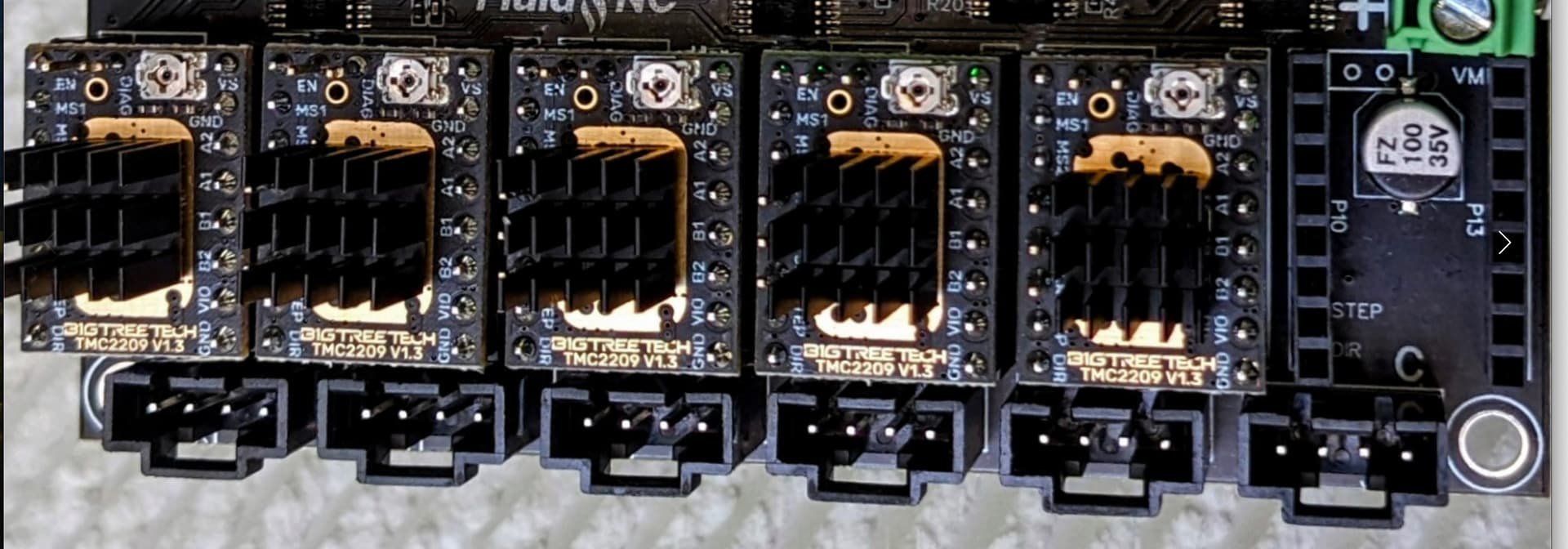
In the picture I’m quoting below (a crop of the picture at the top of the v1e Jackpot page,) it clearly shows that these are 4 pin stepper connections. In reviewing that, if you already had those 8-pin stepper wire pairs, it would have been a good time to ask in the forums about it. In retrospect this would have saved you a lot of that precious time.
-
any 2.54mm spaced female connector will probably work for you if you can’t find anything else locally.
That’s the thing- at least here, the connectors DO NOT differ from the usual 3D printer. One thing that might make the documentation page better would be some kind of note. Perhaps saying if you intend to use jackpot with steppers/wiring that don’t have 4-wire 2.54mm spaced female connectors to check in with the forum to find a suitable match.