I have basically zero experience with designing or making PCBs. The thought occurred to me that since the Jackpot is open source, one could (if one had the knowledge) design a modified Jackpot that is made for two ESP32’s with one made for operating individually addressable LEDs.
I have no clue whether there would be advantages or disadvantages to this, and no clue where to start to make it happen. My general thought is that it should not be hard.
I am asking because I’ve been asked by PCBway to do a collaboration video in which I have them make me something (at no charge) and I use what they make for me, in a video.
I have no idea on that one either but it would be cool to see! Of course if Ryan was ok with it. The ability to have the ESP run from the socket and not have to mess with converters and all that. And will also need a few outputs from the ESP. On my full sheet LR3 i’m currently using 3 from my ESP32
That’s indeed the beauty of open source, and one surely could remix the Jackpot to add space for a second on-board ESP32.
That said, there’s another brilliant element of the Jackpot, and that it it already has an expansion connector. Why not design an interface using the existing expansion connector to host an LED controller that can be added to the jackpot? (It then immediately will be applicable to the other B.Dring board series as well…)
Cheers to this. The form factor might be a little odd (longer) but this would be pretty easy. A lot easier than trying to move the Jackpot traces around. There is honestly not a lot of room so it would take a significant amount of redesign.
So that gives you power and ground, and 4 separate signals in (4 trigers with each having a long and a short signal so you can trigger 8 events), you have as many out as you need. You will also need to bring in your own power to kick out to the LED’s depending on length.
I believe also that on the ESP32 GPIO 12-15 UART capabilities are present.
I’m not sure if FluidNC has a way to use those to communicate from gcode out to a slave device, but that would be a really useful capability.
Edit to add- aside from gcode to do cool visual effects, you could also use it to convey status from the CNC job. For example, change the LED colors on the LEDs at the core to indicate which tool is supposed to be installed at the moment, or to indicate which type of milling operation is taking place. Or to indicate that you’re supposed to have the touch probe installed now, or that the gcode has high a pause. Etc.
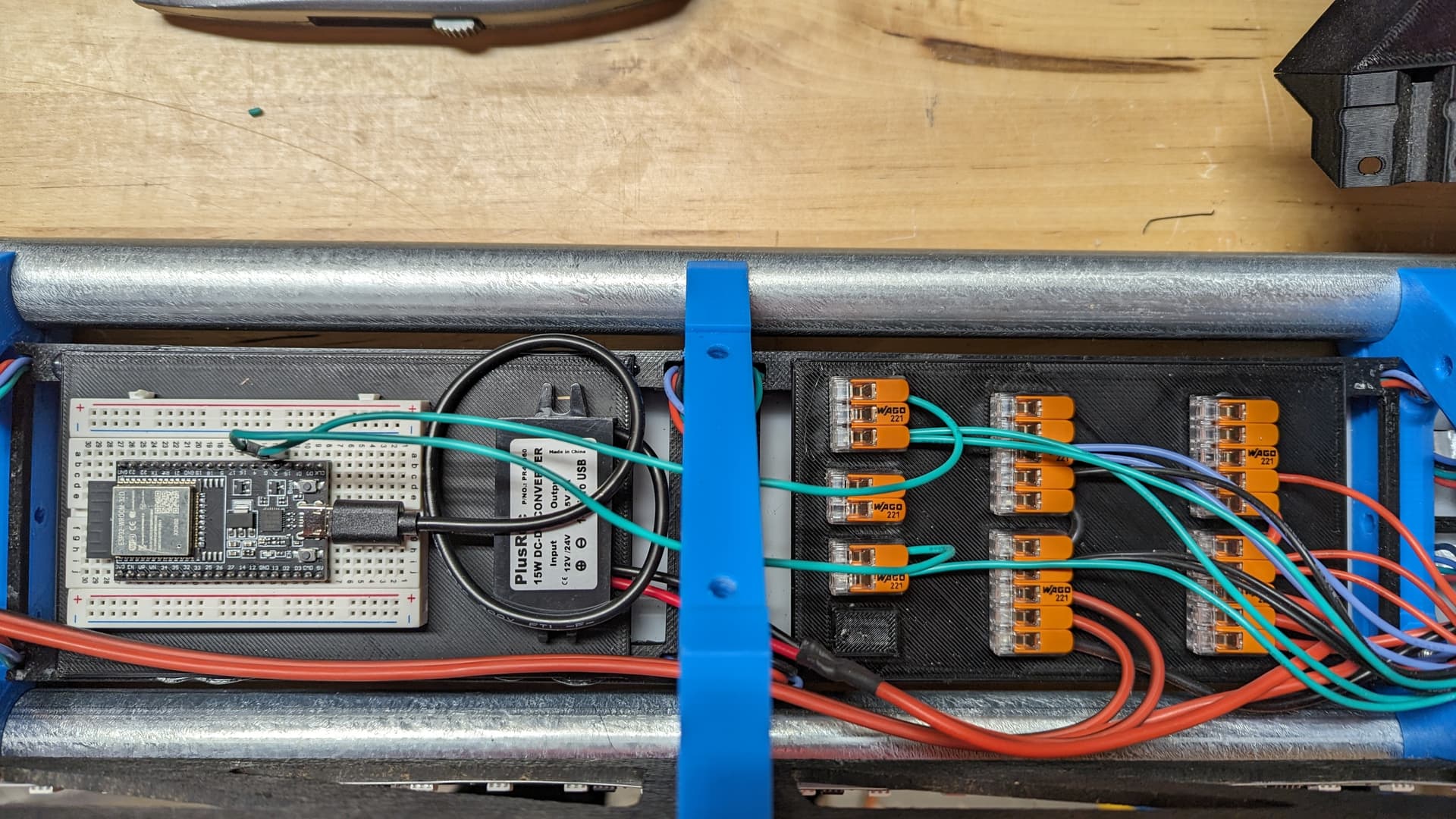
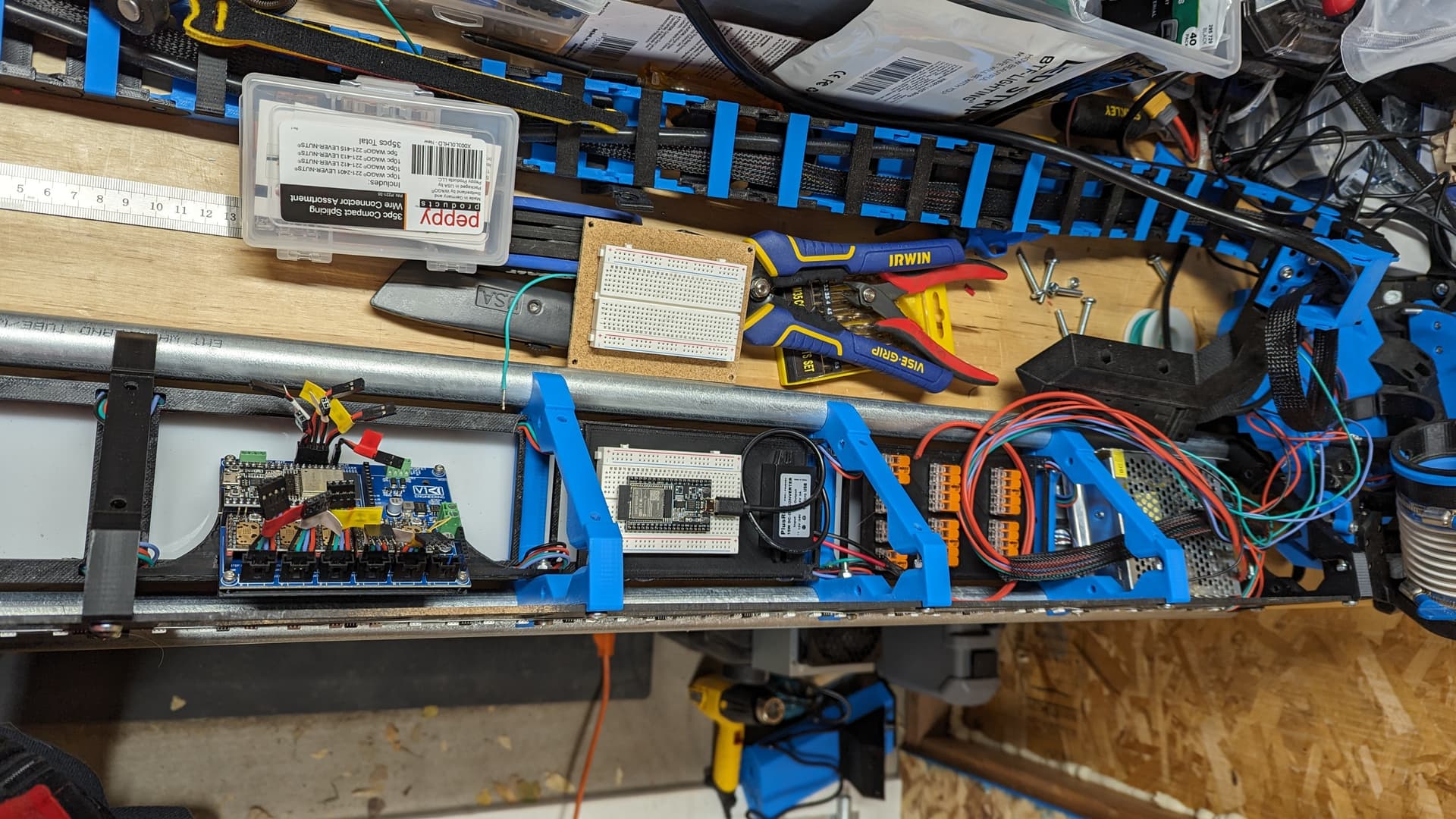
@Jonathjon Since you are using a second ESP32 with a Jackpot, can you briefly walk me through what you have connected to what, and how, so I can start trying to get my brain around what is needed? I know you have power to the LED’s happening separately, but I mean, what from what is connected to what on the second ESP32?
From the look of this, there’s a buck converter that is supplying power via the black USB cable to the ESP32. The only other thing I see coming from the ESP32 in that picture is the green serial wires that go out to the distribution network and then run out to control the strips. This particular implementation is super simple from a wiring perspective.
Edit: I don’t think this is closed loop communication with the Jackpot. I think @Jonathjon controls it via WiFi.
So, for direct communication between the Jackpot (FluidNC) and the LED controller, there would need to. be additional wiring between the two boards, which would be the main thing the expansion board would do. The expansion board could also do VMOT regulation to supply power to the slave ESPE32, and then break out the GPIOs from the ESP32 for whatever the user wants to do with that slave ESP32.
Yes, currently he is just triggering it manually. I am actually playing with using the Jackpot’s outputs to trigger (buttons) on the wled board. Which he has been asking for help with for when he gets home.
So the wled board just spits out data to the LED’s, it needs 3.3V and ground, then up to 4 buttons (with two states) to trigger events. You can do beginning, tool change, and ending gcode insertion, or FluidNC’s new event triggers. On boot stuff and ending stuff. In the end you only need a few connections between the two.
Im not home or i would send you pics and be able to tell you exactly what pins and all. But you are correct both of my LR3s are running jackpot boards and a second ESP32 for LEDs. Right now im pulling power and groung from the expansion slot to power the second ESP32. Thats it as far as they are connected. I also run ground and 3 gpio pins from the extra ESP32 to the LED strips. They are powered by a seperate 12v power supply. I cant remember the GPIO numbers off hand. But come thursday i can send you pics and let you know for sure.
this is correct
Im actually running my ESP32 from 5v to the vin pin. But i dont see why it wouldnt be just as good running 3.3v as well.
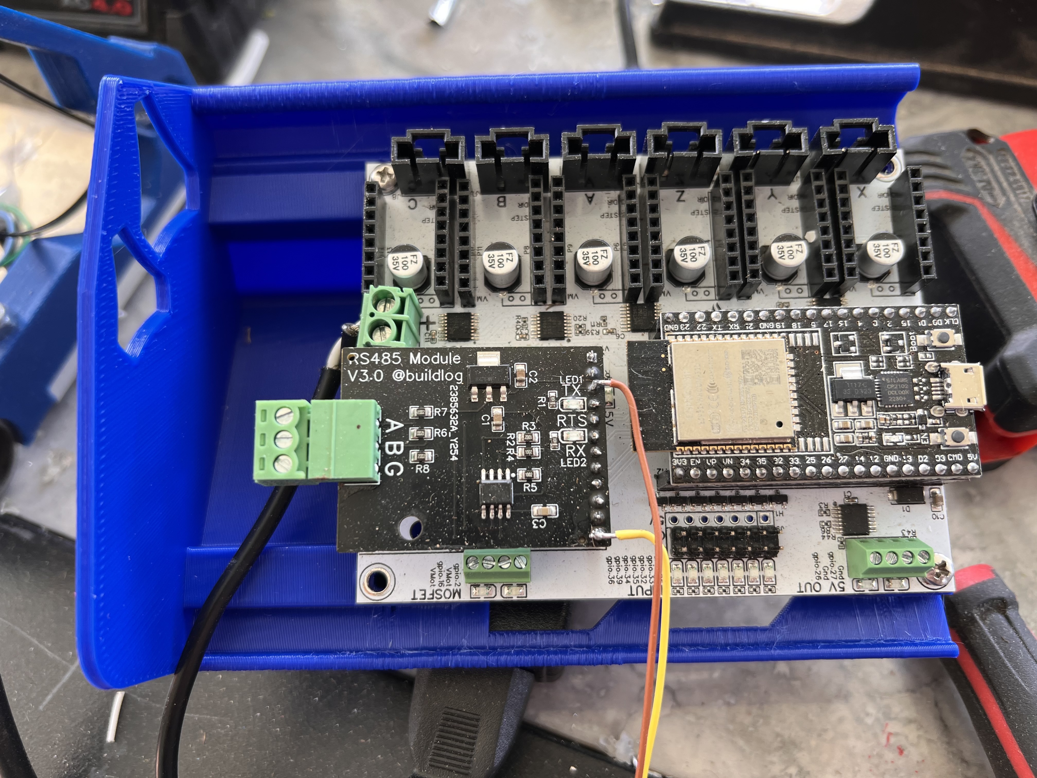
Another thing to think about here (at least in my use case) is on my full sheet machine im already using the expansion port for a RS45 (i think thats it) card to hopefully set up spindle control once i get it all put back together. I also have another card like that to put on my smaller machine for its VFD as well. So Im not sure that having the second ESP32 in the expansion slot would work out for my use case. But I will for sure help in any way with the testing or info that i can. It will be a while before i mess with spindle control on the smaller machine. It will be running the Kobalt (If it ever shows up) for a while i think.
Pic of where im getting power on the jackpot for the full sheet machine. I’m using the same spot on the small machine but no card in it yet. So its just DuPont wires into the correct ports on the header
Im very curious to see how this works out! Hoping i can get it to change for when i need a tool change and for when the job it complete. Then back to its start up settings until the next job it ready. Thats how i had the small one running off the SKR. It was much easier in marlin, but I dont at all regret switching over to the jackpot!!!
So the ESP32 WLED expansion card should also provide for something like RS485 out to a spindle. Probably still possible because it looks like there are two available UARTs on GPIO 12-15. I guess it’s time to take a peek at the design of that RS485 module to see how it’s designed.
This would be a useful feature.
If you could get both in one card that would be AWESOME for my use case. Not sure how many others would make use of the RS485 since the majority run routers.
My apologies Doug, I got lost in the excitement of having the LEDs included and completely forgot about this part.
Congratulations for getting contacted by PCBway. I truly hope its a good door opened for you and wish you continued success in your youtube ventures. Ive been trying to like and drop a comment on each of your (and everyone else’s on here) videos. My understanding is that really helps the algorithm to send your video out to even more people and hopefully get you more views and subscribers.