Well this question should demonstrate the depth of my knowledge level (lol).
BTW, I have the new jackpot board. I plan on swapping out my SKR on the Primo. I am thinking of a second Jackpot to run the following 19” x 37” laser cutter i am building;
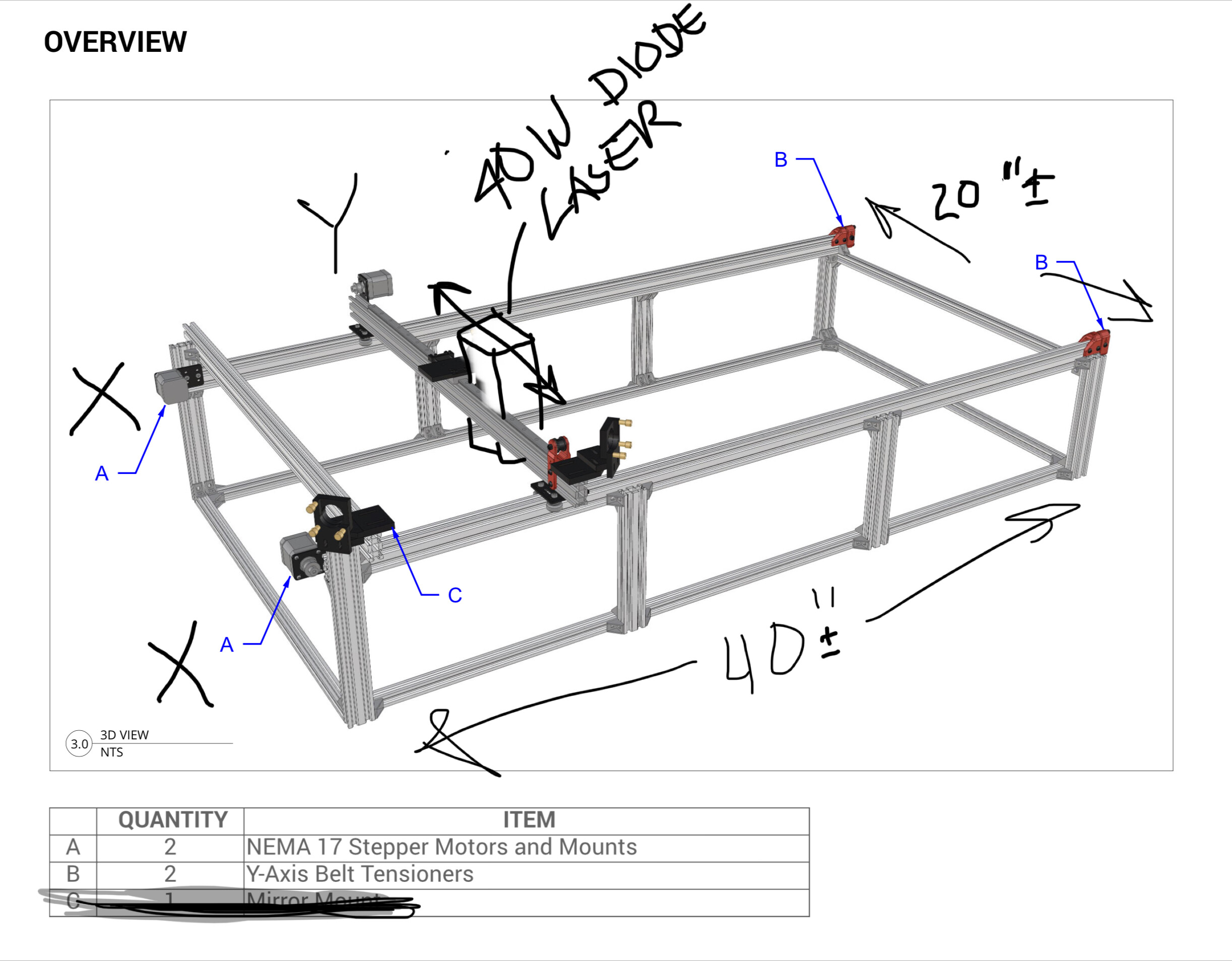
The machine frame based on Future Fabrication’s CO2 laser build, all aluminum construction but I will be running the Longer 40W 8-diode compressed laser module with the following motors.
Nema 17 (same as primo) for Y (moves laser module forward and back on gantry)
Nema 23 dual shaft for X which moves the gantry left to right
I want the zero to be in the lower left like my Primo
Will have manual Z at tool head and might add Z axis with Nema 23 for bed up and down.
From what I gather I will need external diver for the nema 23s and separate power sources. I read where there is a board to separate the power of the motors and laser from the electronics to prevent shorts or other things to damage the controller, etc.
Building the machine is not difficult, getting the electronics set up so the machine can function well that is where my knowledge gap begins.
I’d love someone to tell me exactly what I need to do but I do not mind learning enough to do the job, actually would prefer learning. Having the Jackpot run the motors and end stops and fire the laser being controlled by Lightburn I’m sure is easy enough for y’all to do. I am hoping I am over thinking this as being difficult… what what you don’t know you don’t know is quite intimidating.
Seems to me that it might be more to the point to run a pair of Nema 17 motors for your X axis rather than a single Nema 23. The two smaller motors will likey equal if not surpass the power available from the single motor and will offer significant savings in machine cost and complexity.
I’m at the drawing board for my second original laser machine, and this is where my thinking has taken me. My gantry will be the X axis, but the current plan will be for dual Y axis Nema 17 motors to keep cost and simplicity. I chose the X axis to be lighter because my observation of Lightburn’s fill is to shuttle back and forth in X with small movements in Y.
The interface between the controller and the driver is mostly done with Enable, Direction and Step. If you look at the pinout for a simple one like the drv8825, you can see those, the 4 motor pins, the motor driver power, and the microstep config pins. To use an external driver, you would use the EN, Step and DIR pins (along with ground for reference) and wire up the TB driver (or whatever). The firmware would only need to be configured so it wouldn’t try to treat them as TMC drivers. It wouldn’t know anything after that.
I would look for videos or guides for using the drivers you want with skr boards, or even ramps. I haven’t ever ran with the nema 23 motors, but my understanding was 24V was fine, but 48V was possible. There is also a 6 pack board by Bart Dring for FluidNC that has an external driver adapter board option.
Otherwise, your 2 axis, maybe 3 machine is pretty usual, and doesn’t need a lot of special configuration.
Well, i reconsidered using NEMA 17s and since i have 5 laying around, it seems the easiest solution rather than dealing with external drivers, etc. here is a pic of the basic frame… the CO2 plans for this build rotated the axis 90* so the X was the single stepper gantry and the Y was the dual stepper gantry. This is also the previous version (the new version has the NEMA23 dual shaft in place of the two NEMA17s on the long rails. By me going with the 17s all around makes the build easier and less expensive and more like the low rider so I think I can just follow that build in terms of X and Y and use the Jackpot 32 GRBL…. Please chime in if am going way off base here. As of now no Z axis but will have future possible Z bed movement. The laser module will ave manual adjustment.
Okay you knowledgeable folks… I think the Jackpot should do the trick with my intended laser machine but just because I think that does not mean I know anything about what I speak of… so please treat me as knowing nothing (not far from the truth).
Making the frame and using all NEMA 17s to move the X and Y axis is not so much an issue as I can follow along the LR3 build as well as my experience building the Primo when hooking up the Jackpot. However, I am merely guessing when it comes to using the laser module vs a router.
I have the following info for the laser module.
Longer 44-48W Output & 8-Core Diode Laser Head
Diode Laser Module
size: 81 x 81 x 165mm
Weight: 1.99kg
The Longer B1 machine (which I now have) is equipped with a new 32-bit motherboard & TMC2209 silent drivers.
Power to Machine
input AC 110-240V, 50/60Hz
output DC24V 9A 216W
So, to use the Jackpot to control the laser, is there documentation or video that layman can understand on how to hook up what where? Or does someone feel philanthropic enough to tell me what to do? LMAO… as if y’all don’t do enough freebie stuff, right.
I can learn and follow directions, problem is I don’t know enough to figure it out on my own.
Most V1 documentation is very “layman” in nature. Some of the machine configuratuons, maybe less so.
Pretty sure I’ve seen posts on exactly what changes to make to run a laser on a Jackpot. The question is what machine you are putting it on. If that will be a Primo (just guessing from your other thread) and you want to also use it with a router, it’s a little trickier, but really not much. Just needs a reboot between mode changes.
Edit: For the other build it will depend on the motor configuration, but a custom profile certainly. So long as you are using NEMA 17 motors, the Jackpot will do a great job (Just re-read the thread.) I mentioned that I have a laser on the drawing board (Now with actual parts in hand, lol) and a Jackpot is in the running for control of it.
yup to the docs for V1… hence my ability to successfully build the primo.
I decided to stick with dual 17s y axis steppers and seems to be more designed after the LowRider 3 in that the short axis is the X and the long is the dual Y… reserving Z for later. it will be a stand-alone machine build for the laser. I have ordered my aluminum extrusions and fasteners and will begin assembly when the parts arrive. do you have a build post for your laser machine build? love to follow it.
Have you seen @dkj4linuxManual Z axis for cheap diode lasers? I was quite tempted to use that, though my success at printing the lead screw has thwarted me a couple times. I might give it another try though.
yes, that is what gave me the idea to just build it with XY and get the laser to fire correctly using Lightburn as the control software… then tackle the Z… which in my case would consist of a bed to lower when I need more space. otherwise, I’d still do the manual focus for the laser. and I have even thought it better to build the bed on lead screws (four corners approx) and have a separate switch to turn motor on and off to raise or lower as desired or even a hand crank. so not needing any real Z axis in the controller/motherboard.
2 drivers for the Y axis. (Though a single driver can do this if you don’t want auto-squaring, or don’t want to bother with end stops. I never did install end stops on my 5W diode laser.)
3 drivers left. How about 3 point levelling for the Z axis? The Jackpot can even support end stops for all 6 motors. Suspend your laser bed on 3 motors, and have a lead screw (or belt, for that matter) driven carriage raise and lower it for a Z axis.
Speaking to the folks at Longer… they said I could use their MB to do the XY but not set up for Z but is already set to control the laser module. How much difficulty is it to run a diode laser module on the jackpot. I’d rather have the ability for Z later when Im ready to build that part. Keep in mind their module runs 24v i believe
While I don’t know the specifics of the Longer, the Jackpot has a perfectly capable PWM pin configuration, and several people have got it working with lasers. It is a slightly different configuration, but if you will be using it for a dedicated laser machine, I would foresee no problems with control.