Hello. On my Jackpot board, one of the stepper sockets went bad. It was the Z0 socket. The TMC driver is fine. So I plugged my Z0 stepper wires into socket C, but I haven’t been able to successfully modify the config.yaml file to make the machine behave normally.
Anyway, I am just going to buy a new jackpot 3 board to replace my current jackpot1 board.
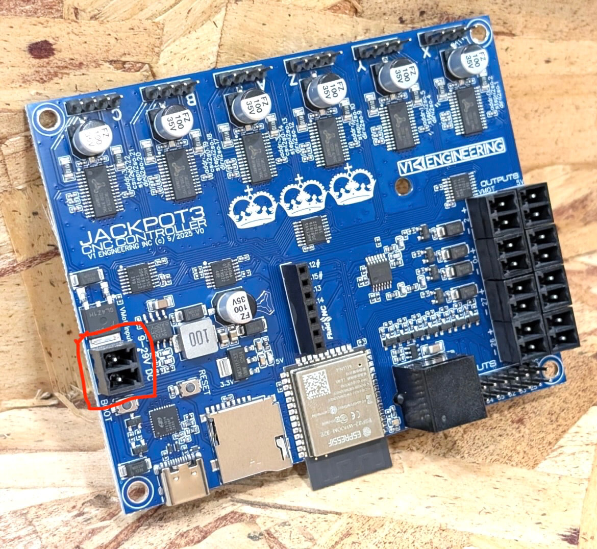
My question: what kind of plug is needed to crimp my 24v power supply to so it will fit the socket outline below? Some kind of JST-XX socket I am sure but could not find a visual match.
The board comes with 5 of those plugs. You just strip the wire back some and the plug has a screw terminal on it. It is highly suggested to put a ferrule on the end of the wires.
If you want to post your config.cfg I know there are plenty here that can help you make the changes to move the Z stepper to C and get you back running with your current Jackpot board.
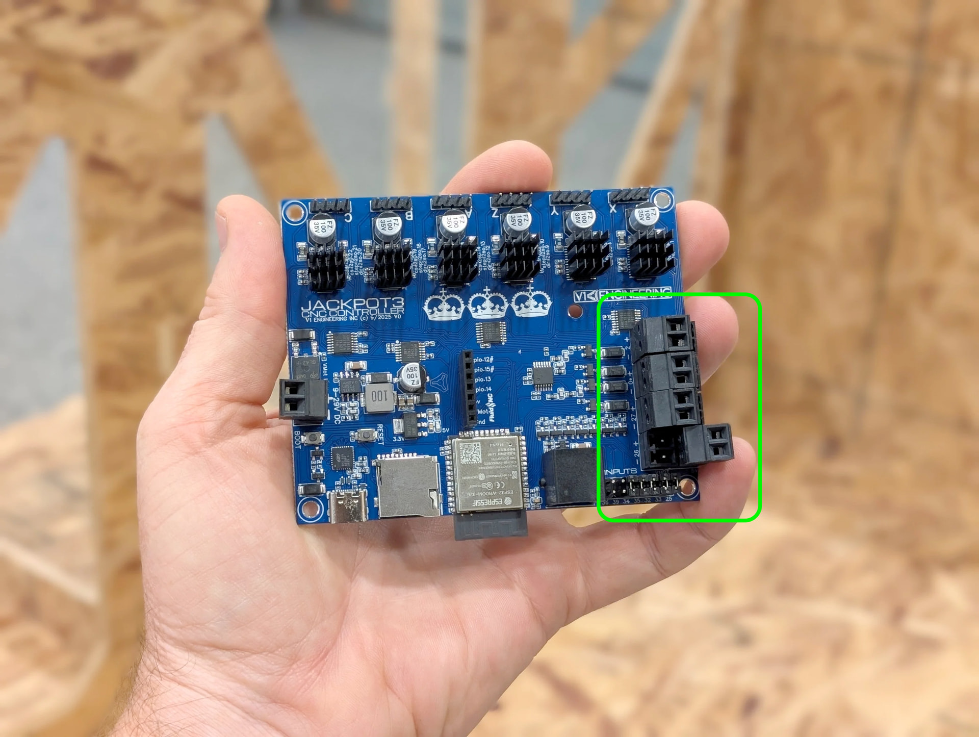
Hey Jonathan, I am actually about to use some of 24v VMOT and some of the 5V outputs for accessories such as 24v relay and 24v LED strip.
Still curious about the best connector plug to connect into those outputs. I bought some JST-VH 3.96 but it doesn’t seem like they work. Are people just using 1P female duponts?
If you mean use the VMOT power to run things through the IOT relay- DON"T pull it off the Jackpot. Use terminal blocks or solder / crimp to pick off VMOT power before it goes into the Jackpot.
Your Jackpot V3 board should have come with the suitable connectors in the box with the board.
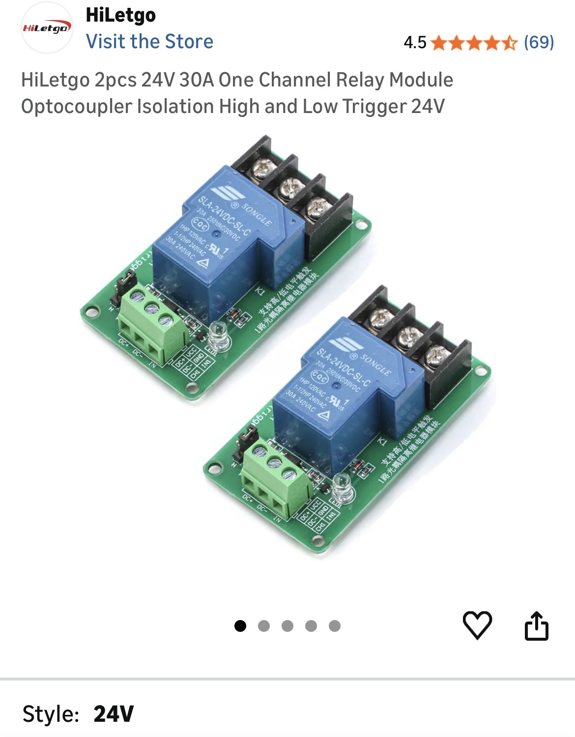
Well I bought this relay to trigger my shop vac and I was going to used one of the VMOT + & - pairs to connect to the DC+ & DC- on the relay and then use one of the spare gpio to connect to the IN on the relay. Hoping the vac will turn on when spindle turns on. I was going to cut the shop vac cord and plug the ground into the relay at the appropriate spots. Does this seem even close? Hahah.
Also I am surprised but I did not receive any of those connectors with my jackpot3. Do you know what they’re called so I can buy some?
Using the GPIO output to run the relay coil is fine, it’s designed for that. Note, however, that the Jackpot board is low side switched. If you have issues with control be sure to ask us more about that.
Generally speaking, you don’t want your shop vac ground to be tied directly to the Jackpot board ground.
Preferrably, not even to the jackpot VMOT power supply AC ground.
There’s nowhere on that module that I’d want you to tie the AC ground for your shop vac to.
Ideally, the shop vac ground should run in its’ own cable all the way back to the wall outlet.
Same is true for the dust collection ground wire if you have one. You want that as far upstream of the Jackpot as is possible (and as far as local electrical codes allow).
Otherwise, you can damage your jackpot with dust collection ESD events, or have odd machine operation due to electrical noise.
Looking at that module, it looks like the load side has a COM, NO, and NC. You want to wire the relay so it switches the line (hot) side of the AC circuit or if you’re using both relays you can switch line and neutral with the two relays. (Or, if you’re in a country with 240V service, both legs of AC).
You do that by bringing the switched leg into COMMON, and wiring the load (Shop Vac) to the NO side of the relay.
I was research this a bit a few days ago and I remember that yes I switch the HOT not the ground. Thanks for the reminder. And use the jumper to make sure it is low switched.
My dust collection hose is actually ground to Huangyabg VFD ground. Hopefully that works ok.
Thank you this is very helpful to clarify everything and so I don’t burn my house down!
I did also find the pluggable terminal blocks on Amazon, I think they’re called 2-pin KF2EDG 3.81mm pitch terminal blocks. We’ll see if they fit.