Issues with Homing and Endstops

Hi everyone, unfortunately, I’m back with more questions. I have searched the internet but I think my novice level needs some feedback. I’m not sure what direction to go but any help would be greatly appreciated.

Hardware I’m using: FluidNC Pen/Laser CNC Controller TMC2209 along with optical endstops (I have not added an SD card yet).

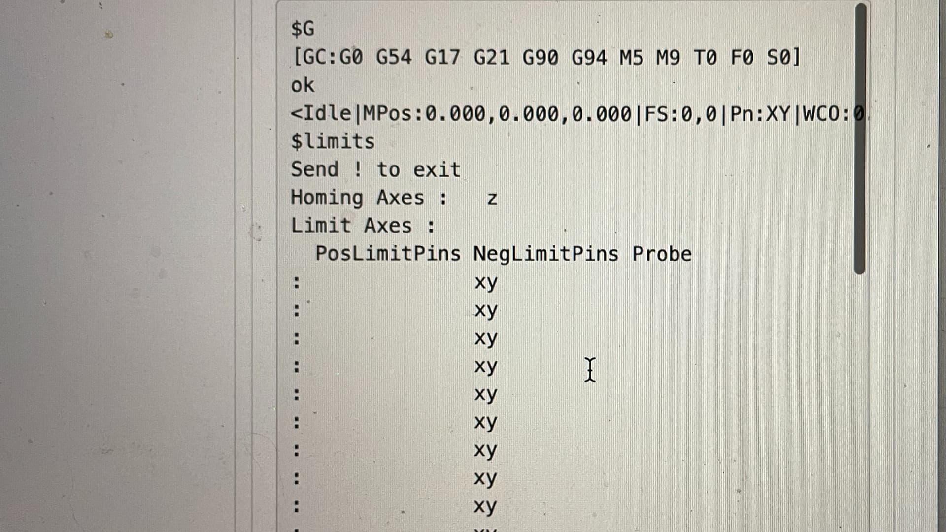
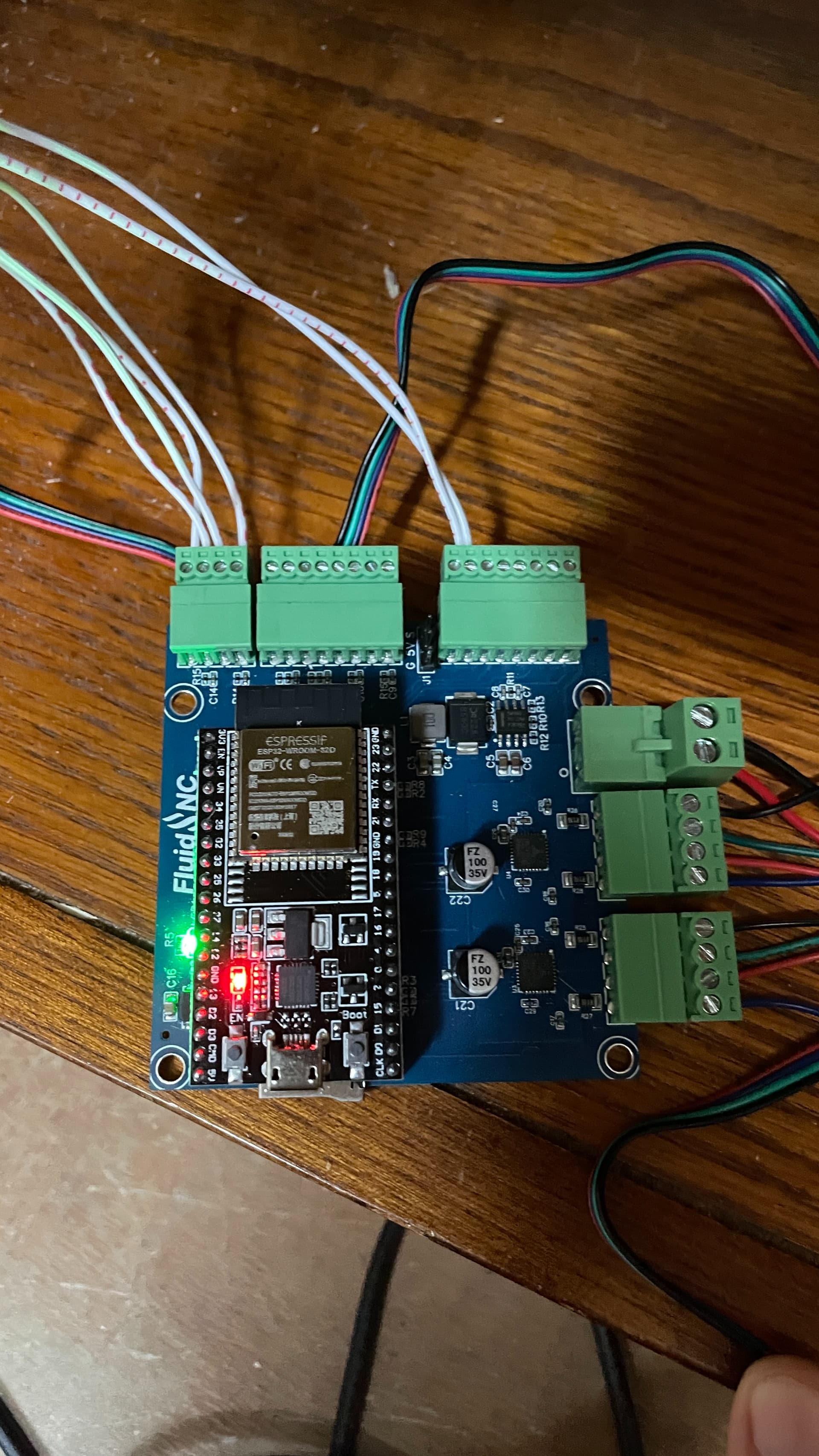
I wired everything up and I have consistent movement from the webui commands moving around the table. I can manually trigger the X axis end stop and it lights up and goes away. However, the Y axis endstop is consistently lit up and I cannot have it stop being triggered. I will post a picture of my wiring. Do I have a faulty endstop? I keep getting error messages saying “Not a homed axis” or “No homing cycle has been defined”. When I send the $limits command, I get pn:xy and neg limits pin tripping the entire time. I read on the V1 forum somewhere that with the optical endstops they have to have the GPIO pin set high as opposed to the default low. Is this my issue?

What should I do?

  1. Do I need to download additional files from Fluidnc or the installer after purchasing it from the shop? I was hesitant to do so only because it plugged and played right out of the box.
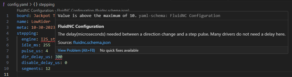
  2. Do I need to edit the yaml file and adjust the gpio settings? I am struggling with this because it’s my first time using fluidnc so I couldn’t figure out how to edit/access the yaml file. This might be due to #1 that I haven’t installed anything additional.
  3. I also read somewhere that someone was having issues and it was due to not having the kinematics group at the top level. When I access the fluidnc webui, I don’t see this listed anywhere. If this is my issue can someone tell me how to add this?
  4. Looking at the $limits command, I see that homing axes: Z and limit axes is blank. Is this the culprit? How do I adjust these?

I realize that these issues are pretty broad and I’m happy to share any additional information. I just don’t know what I should try next. Thanks again.

This is what I get running the limits command:

@WickedRascal

Post your .yaml file so we can look at the settings. I have the same controller and don’t see this with the mechanical stops. I;m not sure how the optical stops work, but I seem to remember that they are powered, and that can cause cause some issue.

Someone will pop in here in a bit with the answer, but it would be nice to see the .yaml file.

Mike

1 Like

Sure here is my .yaml file. After changing some of the config stuff I’m running into new errors such as gpio.14 cannot be written. I’ll check my wiring connections again and see what’s going on. Thanks for answering so quickly Mike!

name: "TMC2209 XY Zen Table"
board: "FluidNC Pen/Laser 2209"

stepping:
  engine: RMT
  idle_ms: 255
  dir_delay_us: 1
  pulse_us: 2
  disable_delay_us: 0

kinematics:
  corexy:
  
uart1:
  txd_pin: gpio.17
  rxd_pin: gpio.16
  rts_pin: NO_PIN
  cts_pin: NO_PIN
  baud: 115200
  mode: 8N1

axes:
  shared_stepper_disable_pin: gpio.13:high
  
  x:
    steps_per_mm: 100
    max_rate_mm_per_min: 2000
    acceleration_mm_per_sec2: 25
    max_travel_mm: 940
    soft_limits: false
    hard_limits: true
    homing: 
      cycle: 2
      positive_direction: false
      mpos_mm: 28
      feed_mm_per_min: 200.000
      seek_mm_per_min: 500.000
      settle_ms: 500
    
    motor0:
      limit_neg_pin: gpio.39:
      #Diag pin is gpio.34
      tmc_2209:
        uart_num: 1
        addr: 0
        r_sense_ohms: 0.110
        run_amps: 0.500
        hold_amps: 0.250
        microsteps: 16
        stallguard: 0
        stallguard_debug: false
        toff_disable: 0
        toff_stealthchop: 5
        toff_coolstep: 3
        run_mode: StealthChop
        homing_mode: StealthChop
        use_enable: false
        direction_pin: gpio.12
        step_pin: gpio.14
        disable_pin: NO_PIN
    
    
    motor1:
      null_motor:

  y:
    steps_per_mm: 100
    max_rate_mm_per_min: 2000
    acceleration_mm_per_sec2: 25
    max_travel_mm: 495
    soft_limits: false
    hard_limits: true
    homing:
      cycle: 1
      positive_direction: false
      mpos_mm: 18.5
      feed_mm_per_min: 200.000
      seek_mm_per_min: 500.000
      settle_ms: 500

    motor0:
      limit_neg_pin: gpio.36:
      #diag pin is gpio.35
      tmc_2209:
        uart_num: 1
        addr: 1
        r_sense_ohms: 0.110
        run_amps: 0.500
        hold_amps: 0.250
        microsteps: 16
        stallguard: 0
        stallguard_debug: false
        toff_disable: 0
        toff_stealthchop: 5
        toff_coolstep: 3
        run_mode: StealthChop
        homing_mode: StealthChop
        use_enable: false
        direction_pin: gpio.26
        step_pin: gpio.25
        disable_pin: NO_PIN
    motor1:
      null_motor:

  z:
    steps_per_mm: 320.000
    max_rate_mm_per_min: 1000.000
    acceleration_mm_per_sec2: 25.000
    max_travel_mm: 200.000
    soft_limits: false
        
spi:
  miso_pin: gpio.19
  mosi_pin: gpio.23
  sck_pin: gpio.18

sdcard:
  cs_pin: gpio.5
  card_detect_pin: NO_PIN

start:
  must_home: false

There’s a syntax error in your yaml… Note the colon at the end of the motor0 limit negative pin line.

Edit to add… There needs to be a FluidNC syntax checker!

Edit later to add- Maybe try something like this?

3 Likes

I am fighting hard not to copy/paste it and call it Yet Another Yaml Checker.

In all seriousness, having something embedded or linked to the v1e.com Jackpot pages to allow validating at least the yaml syntax would be a good start.

A full on FluidNC config.yaml syntax checker would be even better (e.g. check that things like GPIO assignments are sane, etc.)

1 Like

Thanks everyone for replying. I really appreciate the help! I didn’t know about this yaml checker until today. I’m still having my Y endstop issue where it’s always lit up. I’m going to dig around a little more and I’ll post again if I can’t figure it out.

1 Like

We could define a JSON schema that describes the FluidNC config file and validate against that.

2 Likes

I haven’t used it a ton, but isn’t there already a full YAML editor and validator specifically for FluidNC built in to the installer.fluidnc.com site?

Just looking at the code for that site, it does appear to have a YAML editor with validation, but there isn’t anything FluidNC specific.

1 Like

Ok, I haven’t looked that close and don’t have a board to test now, but the editor, if I remember correctly, automatically shows you all possible things for FluidNC, so the editor must have some FluidNC knowledge somewhere.

I’ve only used it maybe once though, so I’m don’t remember exactly.

But it should open the door either for using that directly, or taking the work that was done there to do something a little fancier.

Or even just contribute back to that one if it’s missing something so it is still maintained by the dev team.

1 Like

I’m not sure I plan on pursuing this further but I started creating a JSON schema definition for the FluidNC configuration file. In Visual Studio Code, I installed a YAML extension and configured it to use the JSON schema. It will show errors if invalid values are used or required settings are missing, etc.

JSON Schema (partial)

{
  "$schema": "http://json-schema.org/draft-07/schema",
  "$id": "https://example.com/fluidnc.schema.json",
  "title": "FluidNC Configuration",
  "description": "FluidNC Configuration",
  "type": "object",
  "properties": {
    "name": {
        "description": "The name of the configuration",
        "type": "string"
    },
    "board": {
        "description": "The name of the board used by this configuration",
        "type": "string"
    },
    "meta": {
        "description": "Custom metadata associated with the configuration",
        "type": "string"
    },
    "stepping": {
        "description": "",
        "type": "object",
        "properties": {
            "engine": {
                "description": "This determines the method used to generate the steps in firmware. All of your step pins must be compatible with the stepping/engine type you use.",
                "type": "string",
                "enum": ["RMT", "TIMED", "I2S_STATIC", "I2S_STREAM"],
                "default": "RMT"
            },
            "idle_ms": {
                "description": "A value of 255 will keep the motors enabled at all times (prefered for most projects). Any value between 0-254 will cause the disable pin to activate this many milliseconds after the last step. *Notes: Motors can be manually disabled at any time with the $MD command.",
                "type": "integer",
                "minimum": 0,
                "maximum": 255,
                "default": 250
            },
            "pulse_us": {
                "description": "The duration of the step pulses (microseconds). This is the 'on' duration of the pulse. It typically needs an equal 'off' duration. This means the max number of steps per second will be 1,000,000/(pulse_us*2). Stepper drivers will have a minimum required time length for pulses to register them. If the menufacture provides a datasheet for the stepper driver, this value can be found there.",
                "type": "integer",
                "minimum": 0,
                "maximum": 10,
                "default": 4
            },
            "dir_delay_us": {
                "description": "The delay(microseconds) needed between a direction change and a step pulse. Many drivers do not need a delay here.",
                "type": "integer",
                "minimum": 0,
                "maximum": 10,
                "default": 0
            },
            "disable_delay_us": {
                "description": "Some motors need a delay from when they are enabled to when they can take the first step. This value is the number of microsecond delayed.",
                "type": "integer",
                "minimum": 0,
                "maximum": 10,
                "default": 0
            },
            "segments": {
                "description": "This sets the number of segment buffers. You should leave this at the default unless you are trying to fine tune a special application.",
                "type": "integer",
                "minimum": 6,
                "maximum": 20,
                "default": 12
            }
        }
    }
  },
  "required": [ "name", "board", "meta", "stepping"]
}

I used the information in the FluidNC wiki to create the JSON schema. It would be quite a bit of work to cover the full file. It might be simpler to limit it to a subset of options commonly used on V1E machines.

1. Config file Overview | Wiki.js (fluidnc.com)

This kind of functionality could be done on a web page as well but I didn’t investigate this much.

YAML validation is also a bit interesting since it doesn’t follow all the YAML rules like YAML is case sensitive but the config file is not (i.e. engine I2S_static vs I2S_STATIC).

1 Like

Did you figure this out? Having the same issue. I did read that the tab needs to be trimmed back a bit but I don’t understand why.

This is from the product page:
“These work great on a ZenXY, with one exception. The new fluidnc does not allow for negative endstop travel so you will need to manually trim the endstop flags on the ZenXY to adjust your exact home position. One that is done, everything works as expected.”

Why would I need negative end stop travel.

Hi folks - not sure if you got this worked out since it’s been a bit since the original post, but just in case here was a possibly related issue I had. Cutting and pasting from an earlier post of mine:


Endstops were “sold out” at V1E so I wound up buying the MakerHawk Optical Endstops from Amazon which look identical and fit perfectly into the mounting holes. Big issue with the DLC-32 board that took me too long to figure out - the wires the endstops come with have keyed connectors, that fit both the endstop and the connector on the DLC32 board so they can only insert one way. Unfortunately the pinout is wrong from what the DLC32 wants - the signal and +V lines need to be swapped. Once I figured that out I pulled the pins and swapped the red and white wires and they started working fine.

The 3D-printed Y axis endstop trigger wound up being a bit too short to actually trigger the endstop. I glued a small metal strip (nosepiece from a pandemic mask!) over it to make it a bit longer and that worked fine.


So I’d double check that the wiring is correct vs what your board is expecting…

1 Like