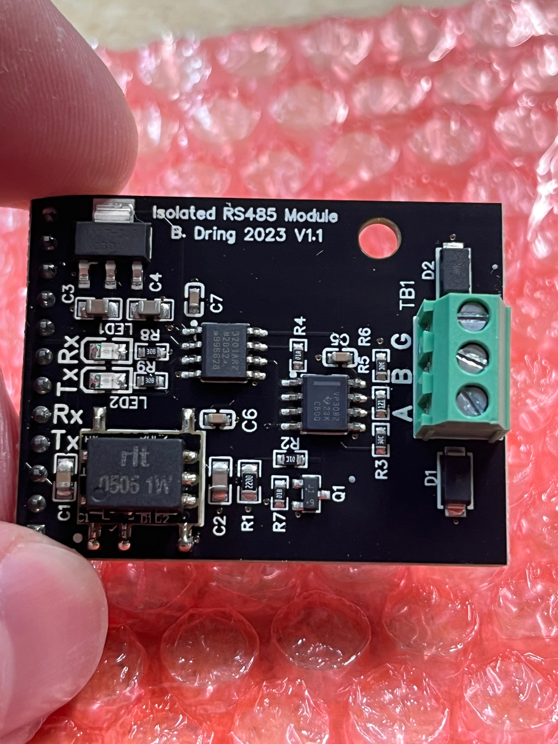
I guess I don’t know too much about Bart Dring’s RS485 isolated I/O module but I know I need it for RS485 communication to my HY VFD. It arrived today.
Curious about 2 things:
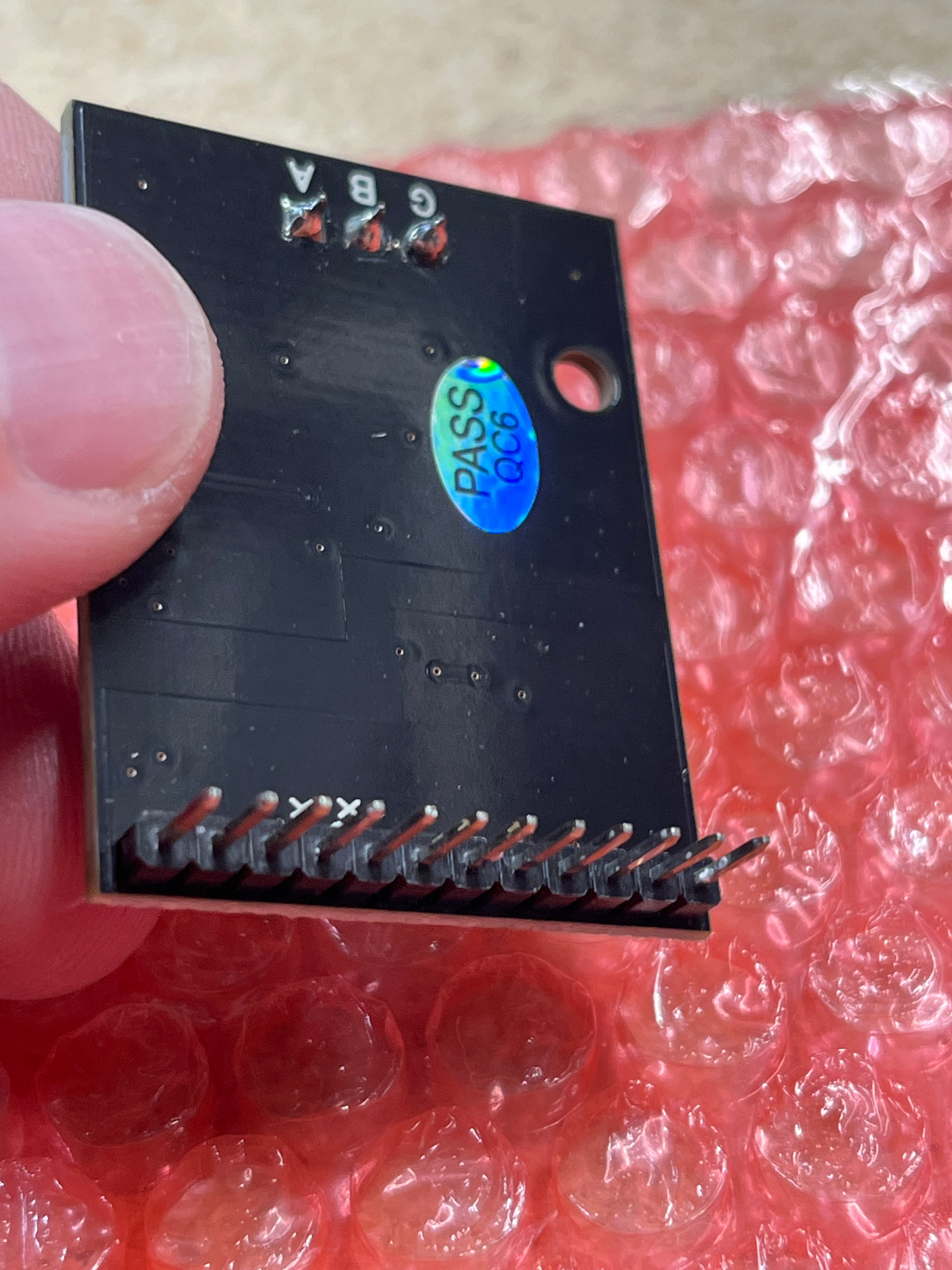
Do I just use 1P male and female duponts to connect this to my Jackpot 3. Do I need to just connect the Rx & Tx pins to certain gpios? What about A B G terminal clamps?
Once you have it wired up, where is the best place to mount it? Should I model and print a vented enclosed for it and stick it to the inside top of my Jackpot Box?
Thats right. If you have the standoff installed in that hole and the IO module screwed into it, the header from the expansion board can only plug in one way. Don’t worry about the pins that don’t have sockets to plug into- they’re not used in this application.
Yes, the expansion IO on Jackpot V1 and V3 use the same GPIOs.
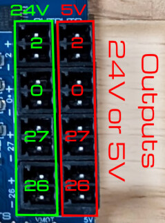
*EDIT: After asking this I continued to do some research and found that the VMot DC- is switchable and is basically an additional gpio meant specifically for relay? So I can just use the Vmot pos and neg pair on lets say #2 shown below, and trigger the relay that way? I wouldn’t need the IN pin on the relay at all. I can switch the relay on and off by configuring my config.yaml file to trigger that DC- when using M7/M8 command on fluidNC?
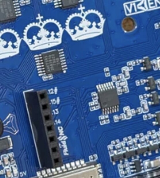
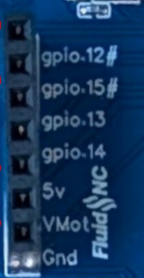
Original Question: Jim I noticed that the RS485 board actually covers ALL the gpios even though it only uses gpio.13 and gpio.14. I need to be able to access gpio 12 or 15 which actually has pins from the RS485 board plugged into it. I know these pins aren’t used but they’re still covered or unusable. Is there a good way to still be able to use gpio 12 or 15 when theyre covered like this?
The expansion module GPIO and the 5V/VMOT GPIO are different GPIO pins, so they are fully independent. The only limitations are expansion module and RJ12 pendant connector- they share pins so we’d have to do some thinking if you want to do both of those things at the same time.
Correct.
I’d need to see the specific details on your relay module to be able to confirm that. If you’ve posted it elsewhere, Its not in this topic so I can’t confirm.