Hi V1-Community,
as mentioned in my 2 other threads I’m getting all organised and checklisted and and and for january to setup the LR3 within the first 2 weeks of 2024 and start learning the ropes after then probably using it intensely from february onward for a bigger project. So I have many questions up front, hoping to “smooth-sail” through the build…
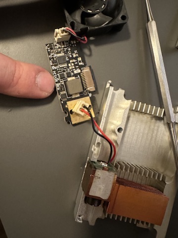
I have an old laser head lying around after I took it out of my Lasercutter (I upgraded to a stronger laser).
It is just a 5W diode laser, so nothing super powerful but it has worked well for me and will still do the engraving jobs I am having in mind for it, is already fully equipped for an air assist and best of all: I already paid for it a loong time ago. It’s almost like a free tool. ![]()
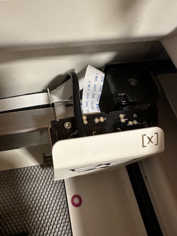
So usually the laser head is connected with one of these flat ribbon raspberry pi camera cables. Unfortunately usually these heads are not sold to regular customers so all I got is a Pin-Outso I know what goes where and the rest is up to my ability to figure it out and make it work ![]()
1 - GND
2 - GND
3 - Vcc (+19V, variable)
4 - Vcc
5 - Digital GND (seperate GND for I2C since 1+2 are “fairly busy” during operation)
6 - i2c clock
7 - i2c data
8 - +5V
9 - +12v (Fan)
10. Laser PWM
They advised me to use a maximum of 70% PWM with 4kHz to not grill the LED.
On the I2C there is also a temperature sensor which they use to pause the program and cut power to the diode if it goes above 60C to let it cool down.
I have attached a picture of the disassembled laser diode with the PCB and the ribbon cable.
My question concerning hooking this head up to the LowRider:
I can skip most of the PINs beside the 19V for the diode (it can take up to 24), GND and the laser_pwm, right? If I connect the Pin 10 to the Laser PWM Pin on my board and set it up more os less like this, connect a decent power supply for the laser and arrange for a common ground so the PWM works, am I at least on the right track? ![]()
Laser:
  # my old mr beam laser head
  pwm_hz: 4000
  output_pin: gpio.27
  enable_pin: NO_PIN
  disable_with_s0: false
  s0_with_disable: true
  tool_num: 0
  speed_map: 0=0.000% 255=70.000%
  off_on_alarm: true
Is the 70% correct there? I am uncertain about exactly that.
Of course if the magic smoke goes out of the laser, it’s entirely my fault, so feel free to pour in your suggestions, even if they turn out to be a bad idea later ![]()
Have a nice evening everyone ![]()