I understand that I can just rotate the object in Estlcam, but I don’t want to do that because I want to have it oriented in a way that it is easy “viewable” on the screen Is this possible to achieve?
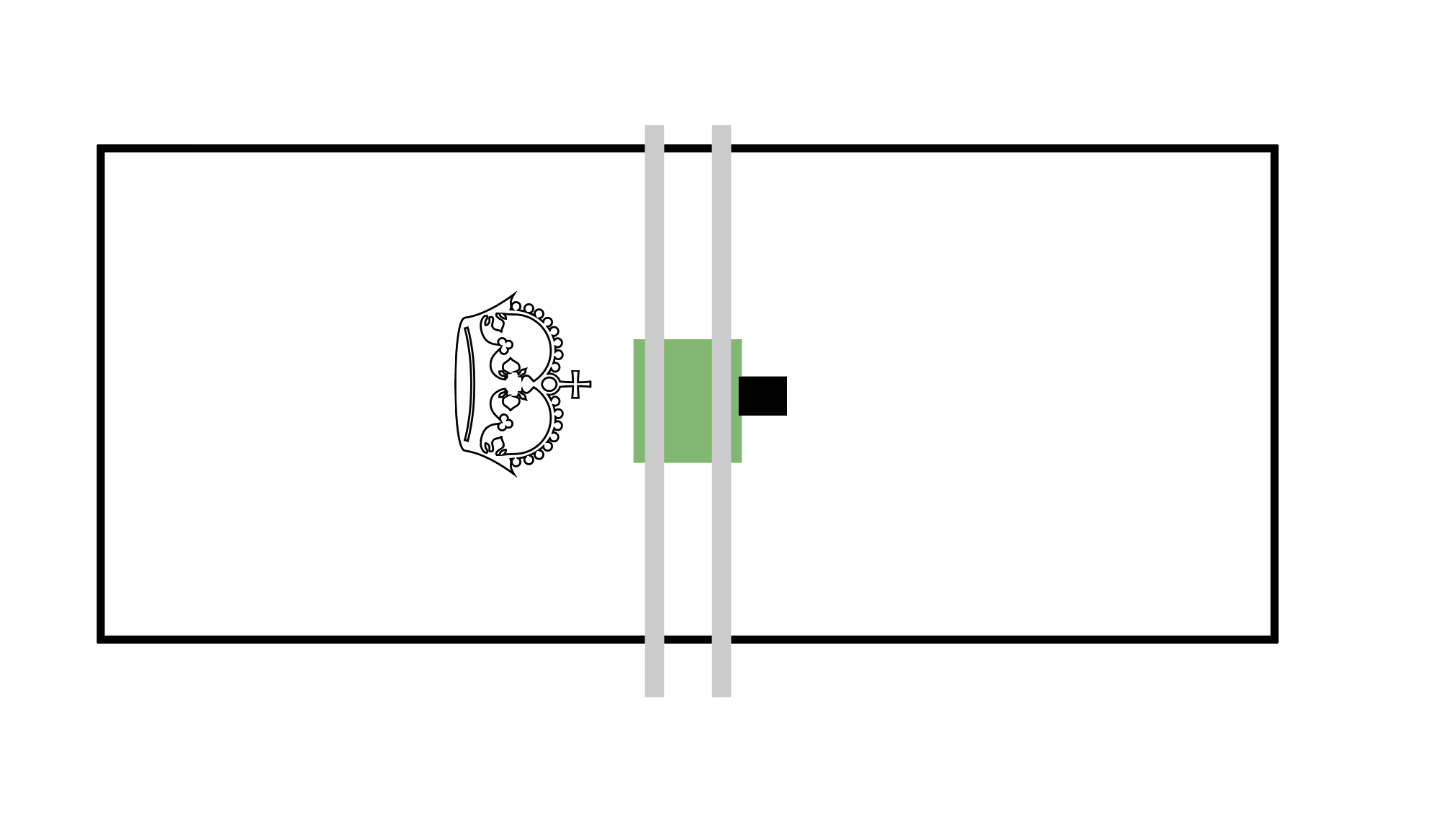
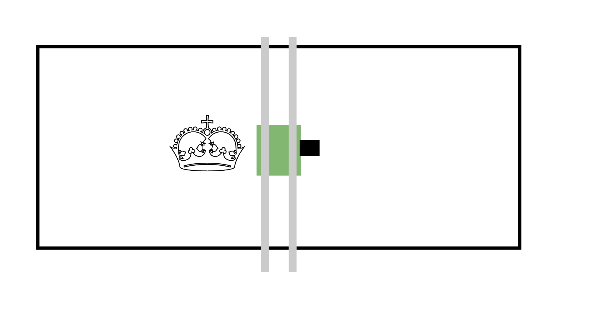
Mine operates the same as yours, but then I also visualize the “page layout” that way on my Lowrider. That is to say that, using your first diagram as an example, I have the top right corner of your sketch as the home point, and Y is my long axis. So, when I use EstlCAM, I see the top left corner of the screen (imagine rotating your top sketch 90 degrees counterclockwise) as the home position.
Those with more experience will chime in, but I imagine you could achieve what you want by re-connecting your stepper motors so that the short axis is X and the long axis is Y.
Yep, this is the solution. I encountered this same thing with mine and also wanted the items to cut logically for orientation the same way I draft them, and see them in estlcam. It eliminates some simple errors when setting up your cuts.
Swapping the stepper wires works for serial builds, but since we started supporting dual LR configurations in the firmware, we had to pick an X and Y. The instructions use X and Y in the “portrait” orientation and not the “landscape”. So we followed that convention in the firmware.
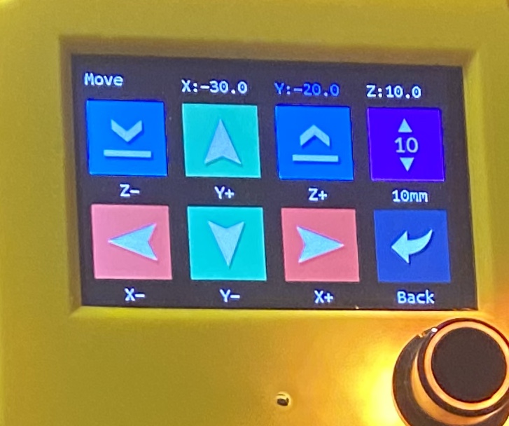
This was the solution for me. If you have a TFT touch screen I would connect your steppers so that it matches what you see on the screen in reference to the side of the table you are operating the machine from. So Y+ would be away from you in this instance. I have no idea if this is correct or typical but it helped me a lot when starting out.
 I have some questions about the axis tho.