Late January we finished up a fairly large project (for myself at least): a garage that was large enough to dedicate some space as a shop. I had about 24x16feet of space to work with. As I have long been a ill-equipped woodworker who never had dedicated space larger than 6ft in any direction, I knew what tool needed to be set up first: a CNC obviously.
I had been researching /watching / learning for a while. I also have had a fairly long relationship with 3D printing so the whole V1 product line was compelling. Then Coronavirus happened.
I am a computer science professor, so that meant that I was spending all of my time in my home office. An office that just happened to have a re-calibrated Ultimaker sitting idle. While Amazon was not shipping quickly, Gizmodorks and V1 were on top of it.
Cutting to the chase, this became my Coronavirus project. It is what kept me busy in between preparing lectures and grading code. There was a span of 3 weeks or so that I spent every zoom/teams/discord meeting trimming brim off of freshly printed parts.
The plans, largely inspired from My LRv2 so far (thanks @wcs39204) :
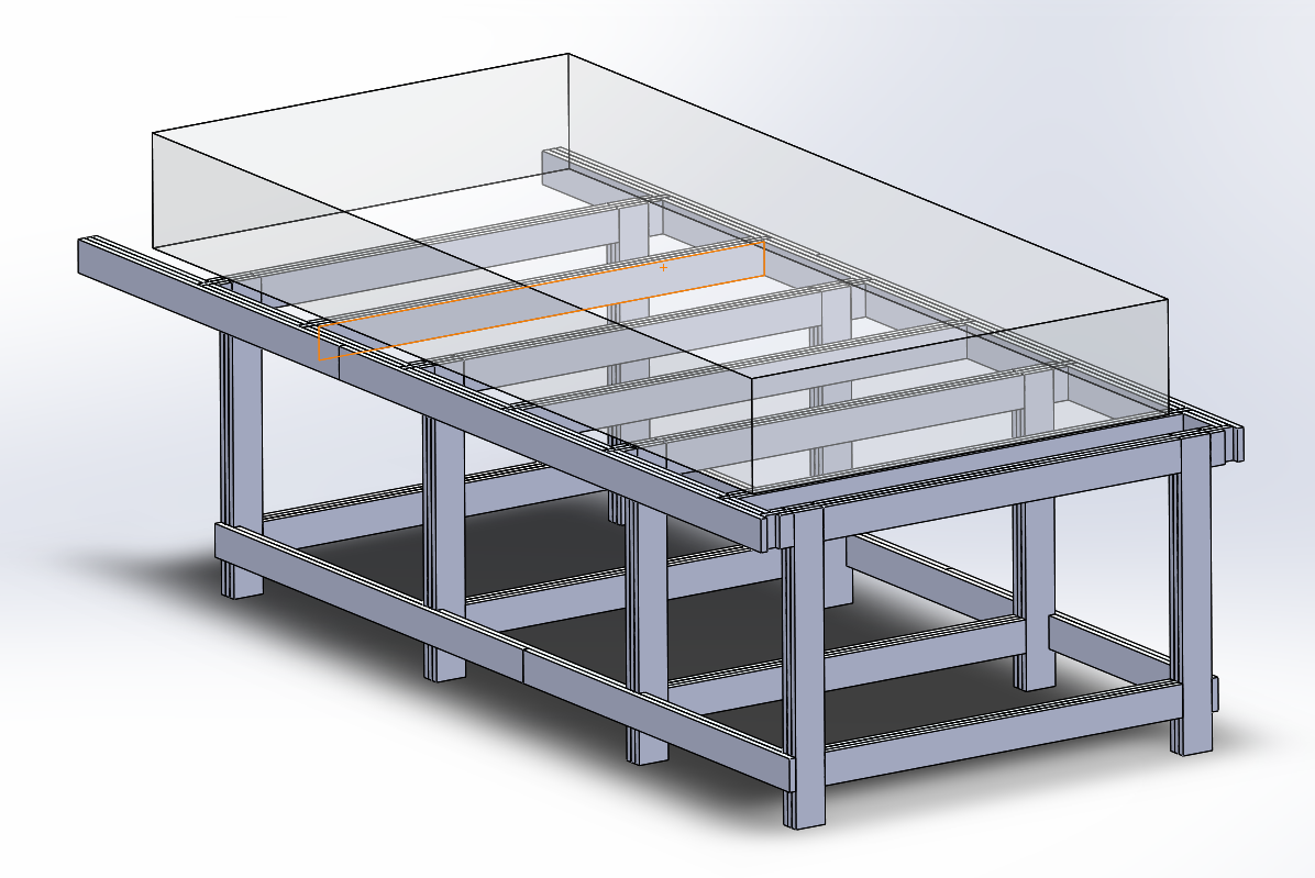
Working area is 50x108 with 12 inch z.
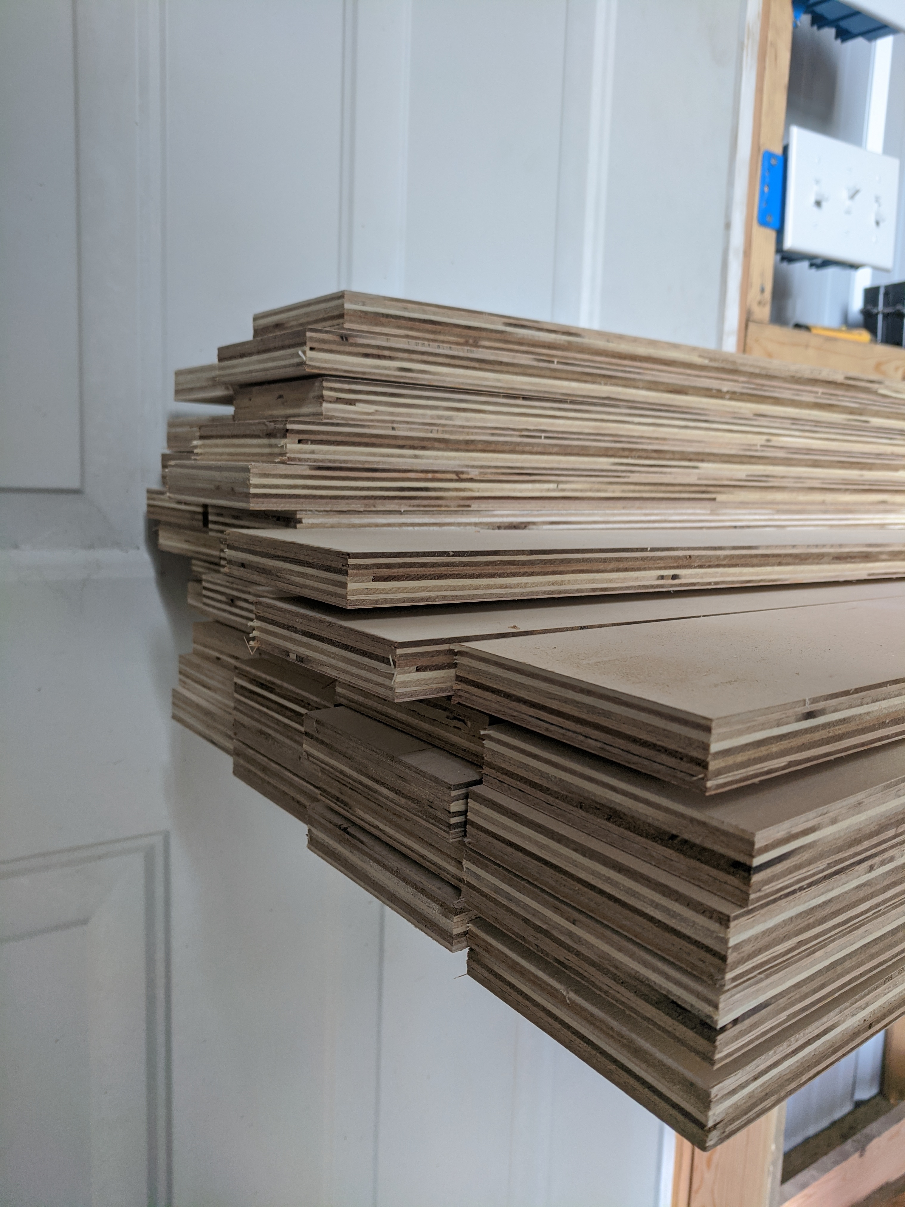
The idea was to use 3.5 inch strips of 3/4 shop grade birch to construct faux mortise/tenon/lap joints. This also meant that I could cut those strips at my dad’s shop on his table saw, then transport them on site and cut to length with a miter saw. Most of the sub assemblies are three layers of 3/4in, so approx: 2 1/4 thick. In total the table took, almost exactly, three 4x8 sheets.
Strips prepped and ready to be cut to length
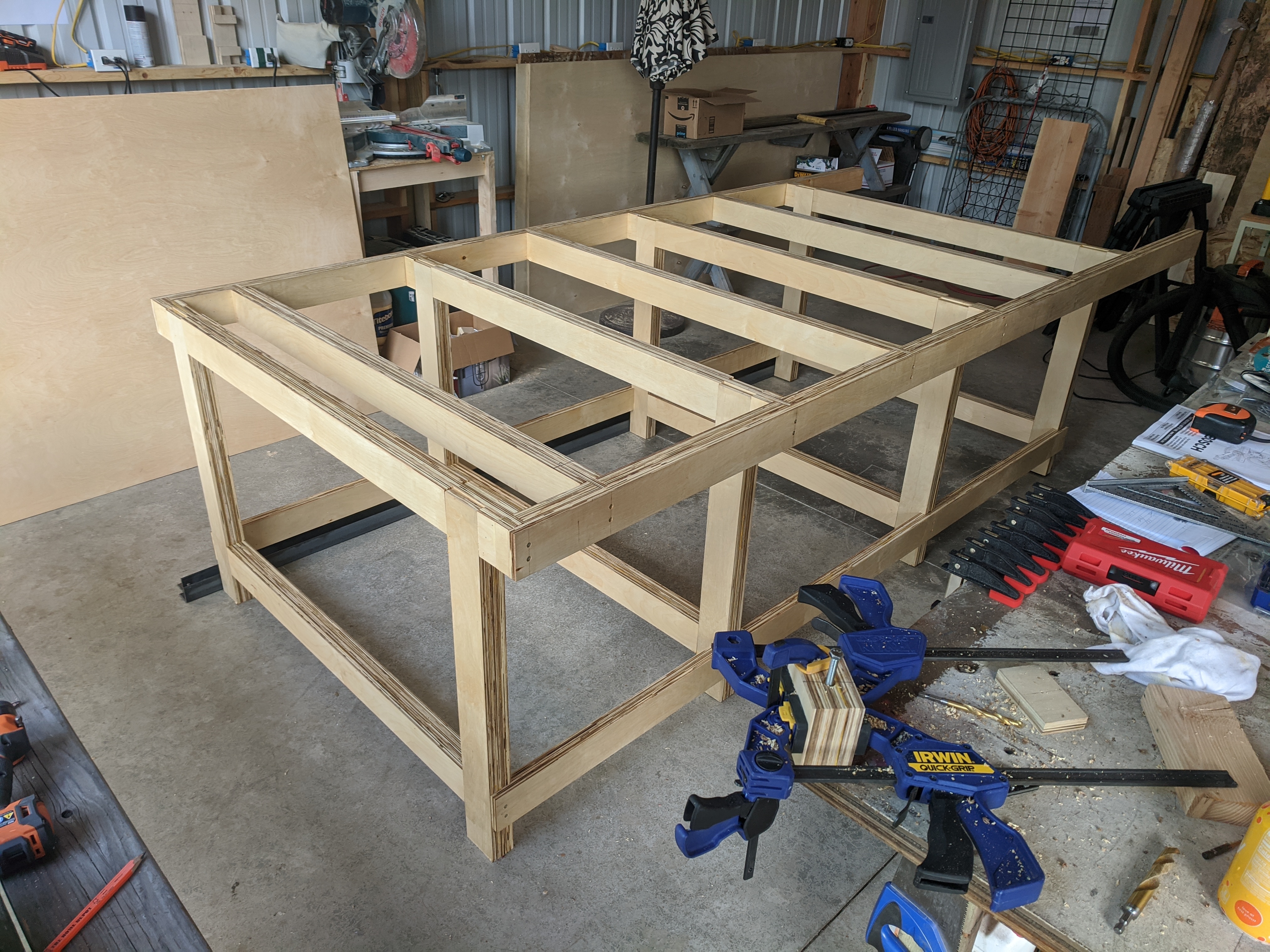
Post assembly, but before adding side rails:
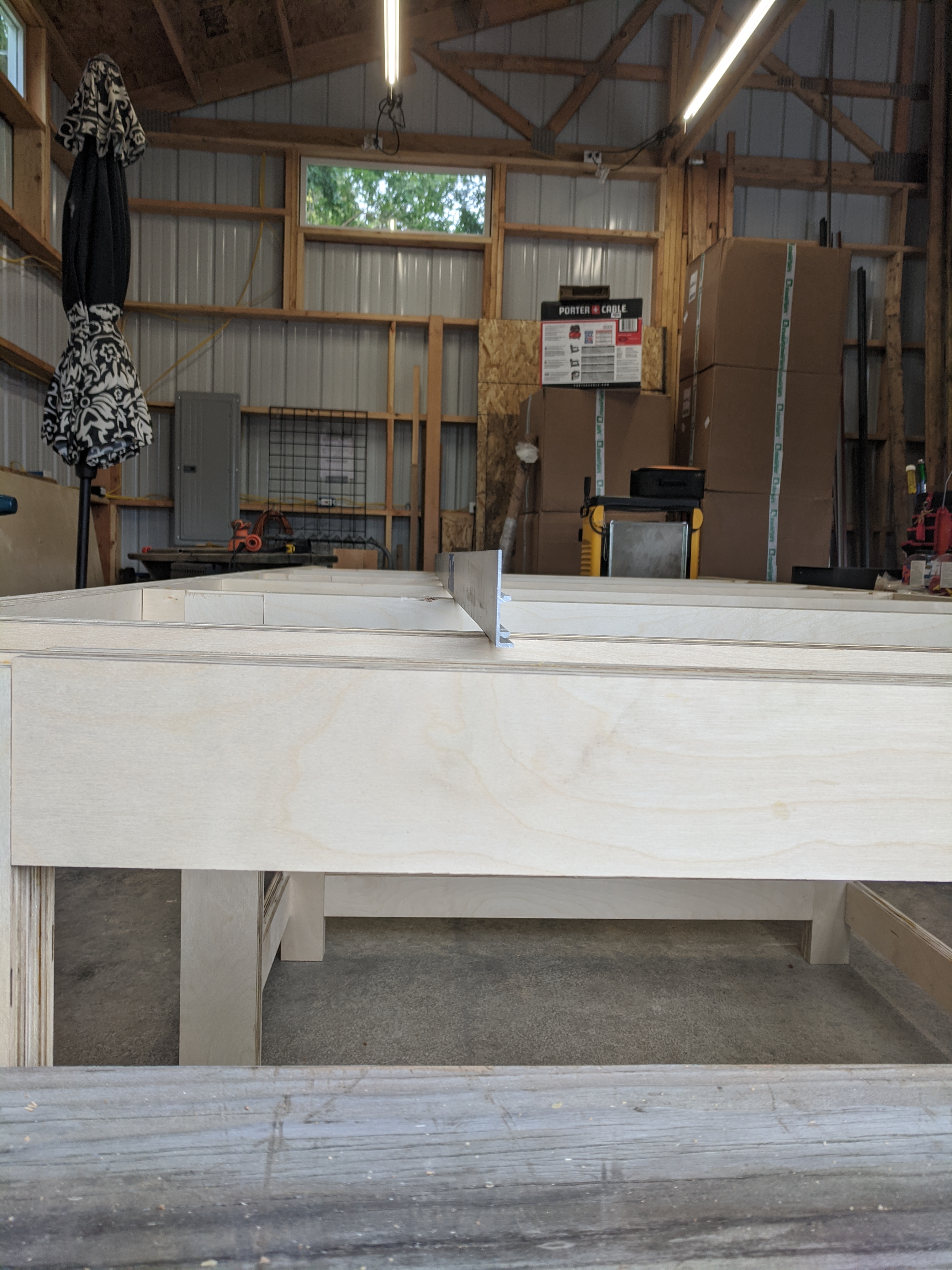
Post assembly level check
The table is made to be taken apart in the event that I move. The long side rails are attached via screws, the inner frames are solid. Everything was coated with a clear wood sealer / finish in an attempt to protect the wood.
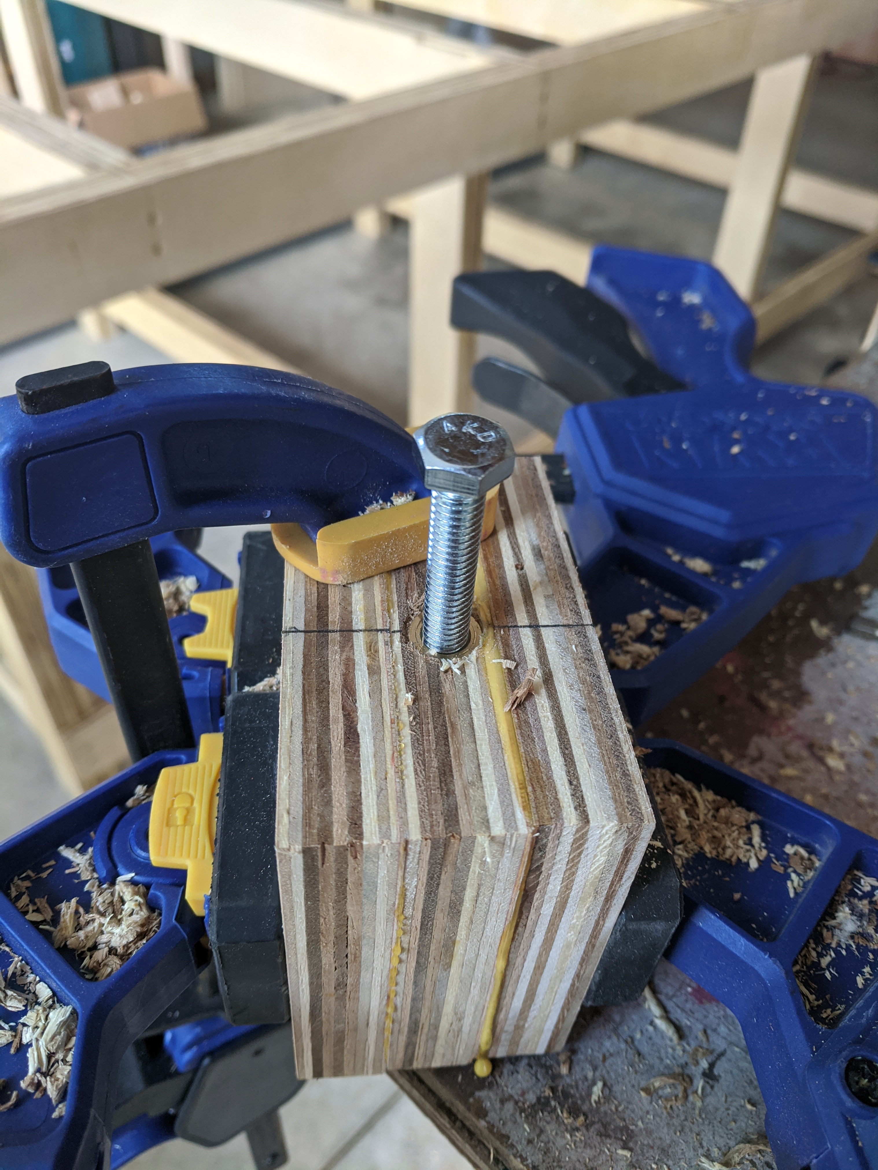
I am using 5/16 threaded inserts to attach the spoil board to the frame. The idea here was that attaching in the end grain of the plywood was likely to cause issues from repeated screw/unscrewing, also as a way to level the spoil board if needed. Each X-axis span has three inserts.
This was my test piece, and has the best detail:
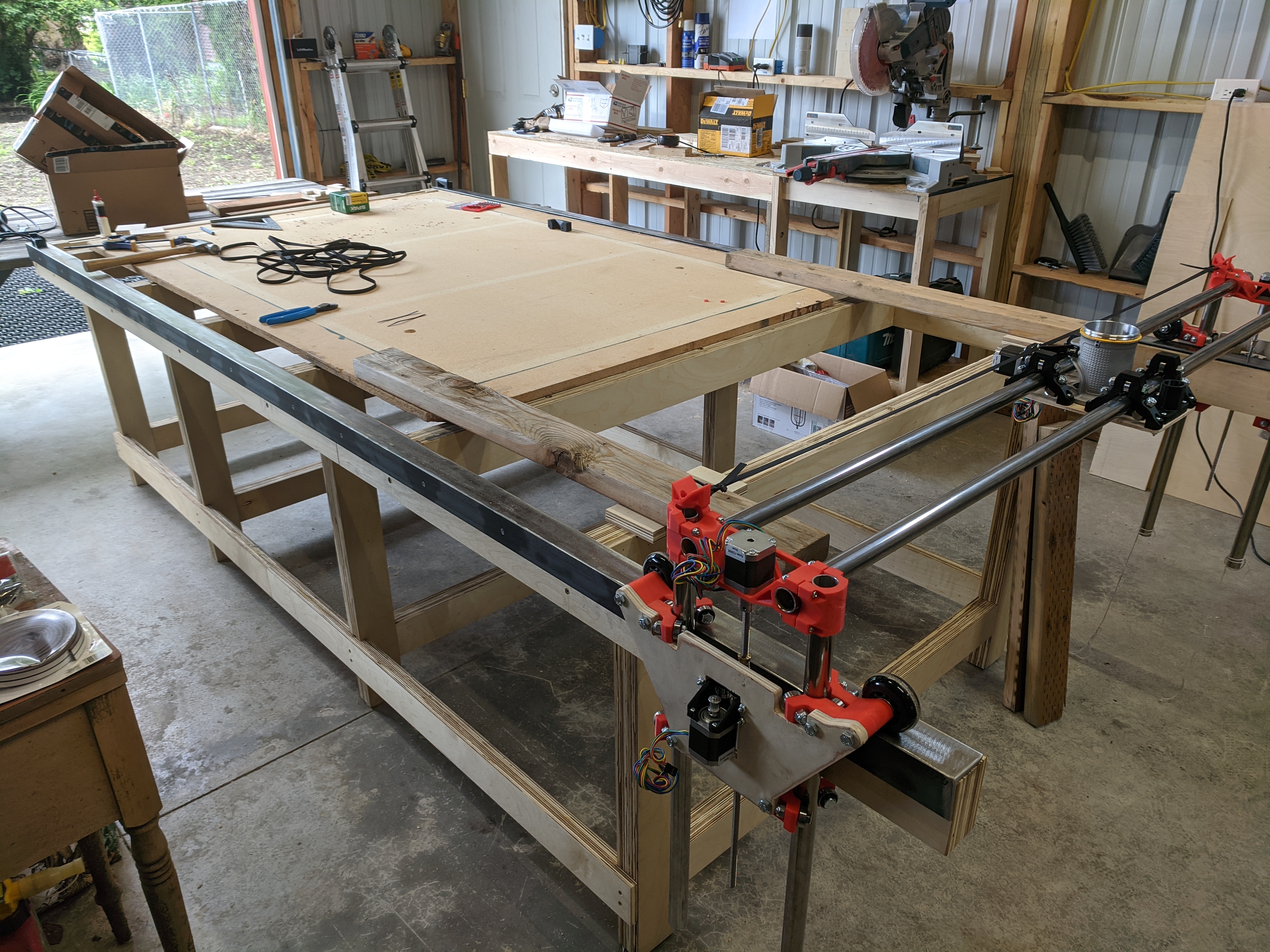
I was starting to get excited and stopped taking progress pictures. Each side rail is ‘capped’ with 2 inch angle iron. This gives a solid (and continuous) top and side surface. These rails are leveled and squared as much as I can get it. Over all there is only a ~5 mm difference between the rail widths from front to back. I was pretty happy with that result.
You can see the rails installed as I started to assemble the gantry.
Almost ready to test:
I purchased longer lead screws and additions belt to accommodate the larger table, but I didn’t really think about the stepper cabling, that is going to need to be modified, things are a little too tight for my preference.
Just an abomination, but for the sake of getting the crown test to work:
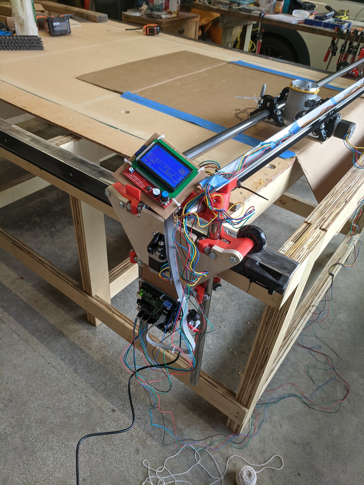
After wiring everything, things looked good. Needed to flip some connectors to get the motors going the right way. Lubed the lead screws, squared everything up, strapped a sharpie to the dust port and tried out the crown:
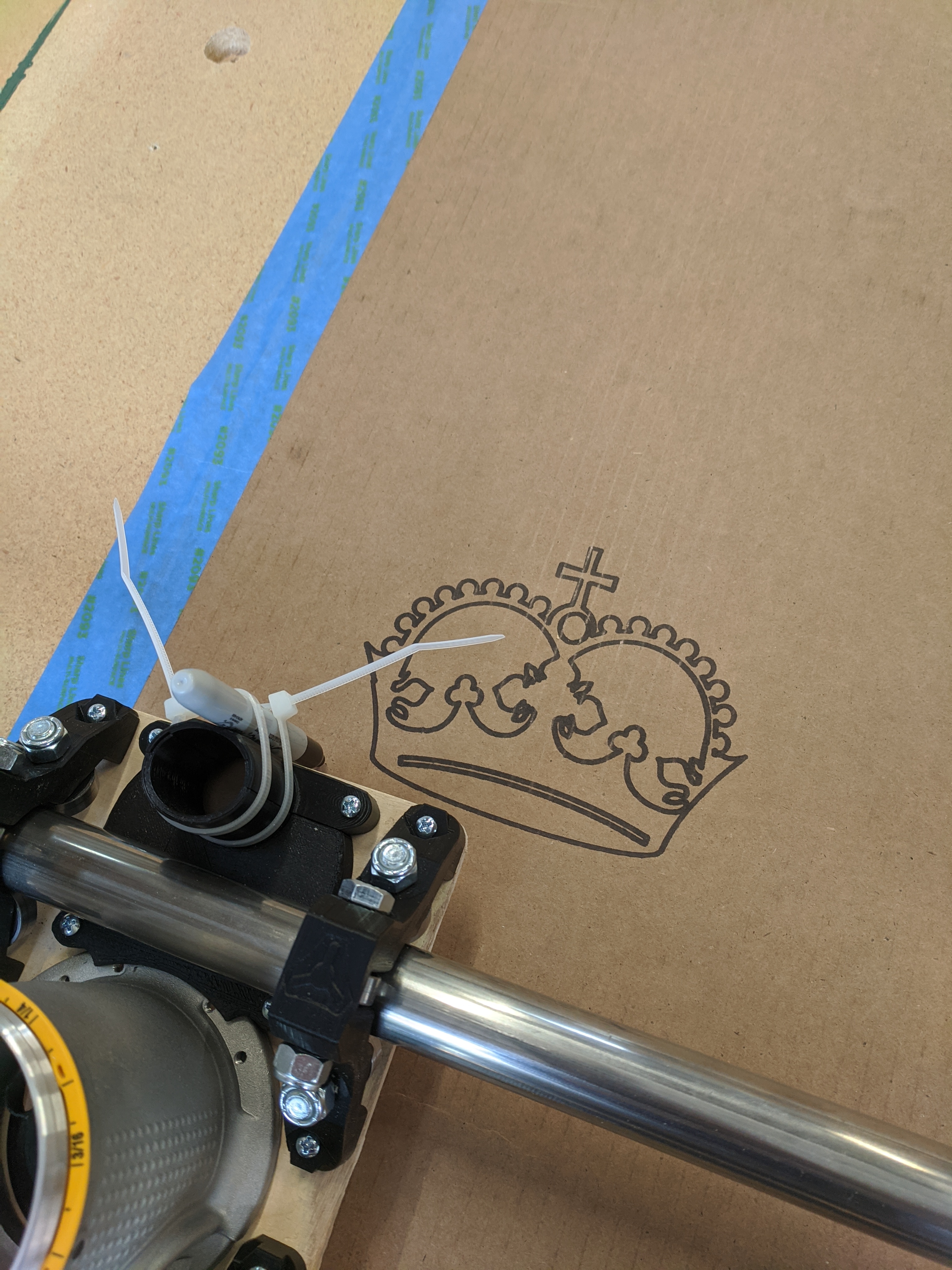
I am over joyed. Most of you know the feeling. Those first, sweet twitters of the stepper motors. It looks like I need to make a better mount for the pen as it was slipping through the first test, but I would say Rona is up and running.
Thank you to @vicious1 and the community at large for the work done on this design and system. I am excited to see what this thing can do!
If anyone wants a more thorough outline of the design (cut list, etc.) I can write that up. Purchasing locally in WA, the wood was ~$150, the iron and aluminum angle was ~$120. The rest was purchased online / through the V1 store.