The idea was to build a full-sheet capable machine, but space is limited for the time being. I am keeping the X-axis at full length and reducing the Y so that I can move to a longer table/pipe someday.
I twisted my wires for noise immunity whenever possible - this made it incredibly difficult to feed through the wire channel in the plastic. Don’t do this.
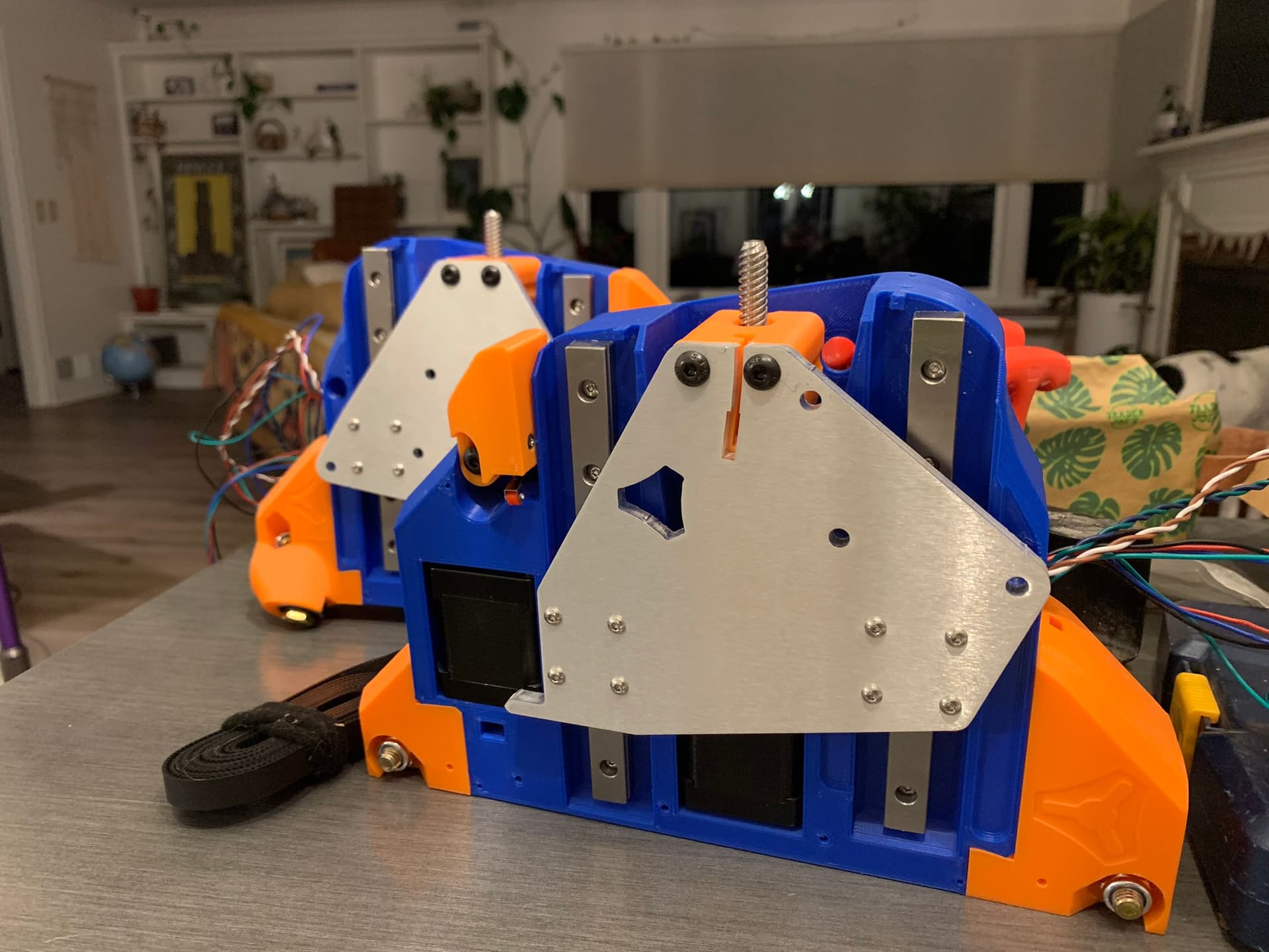
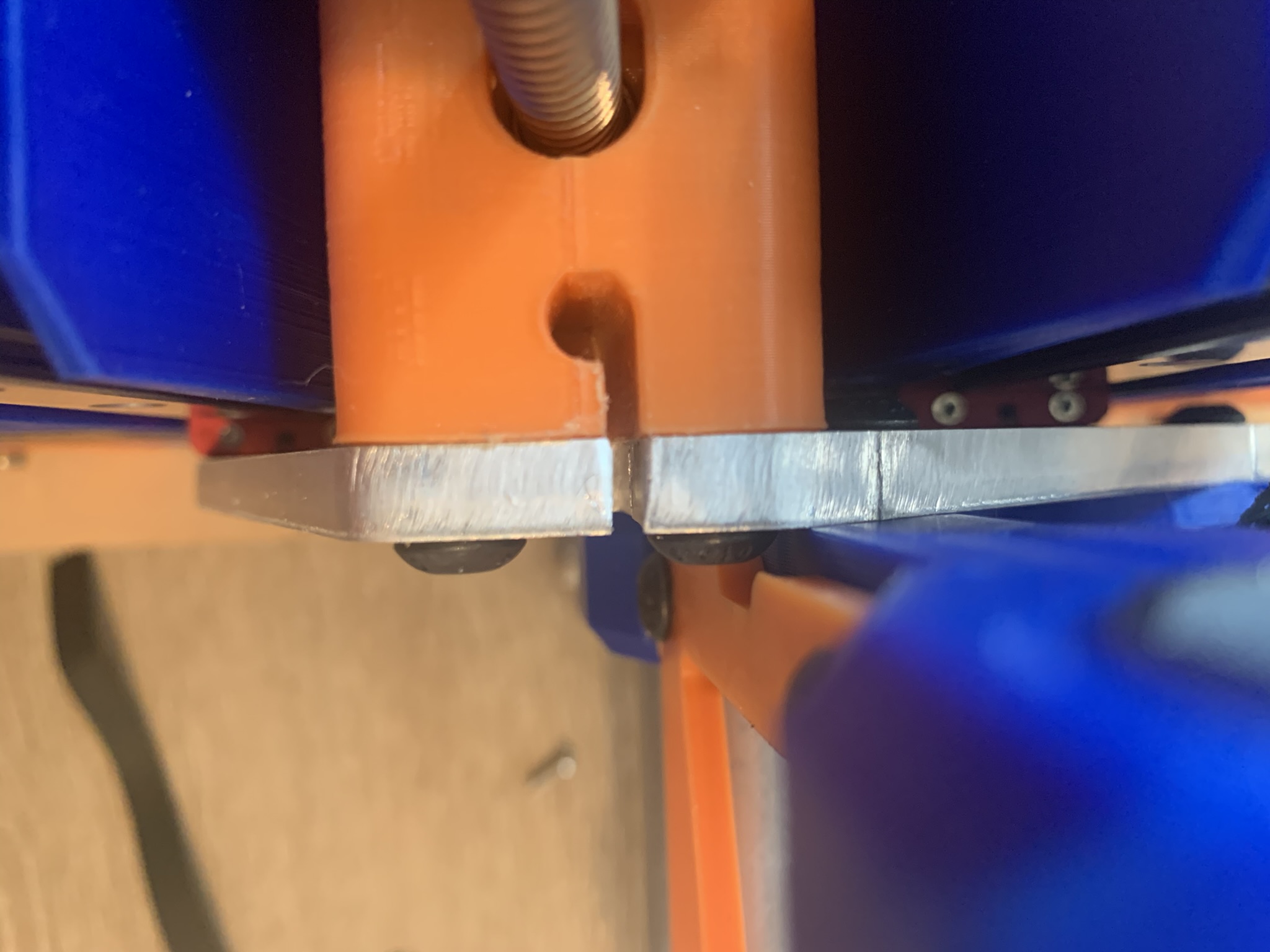
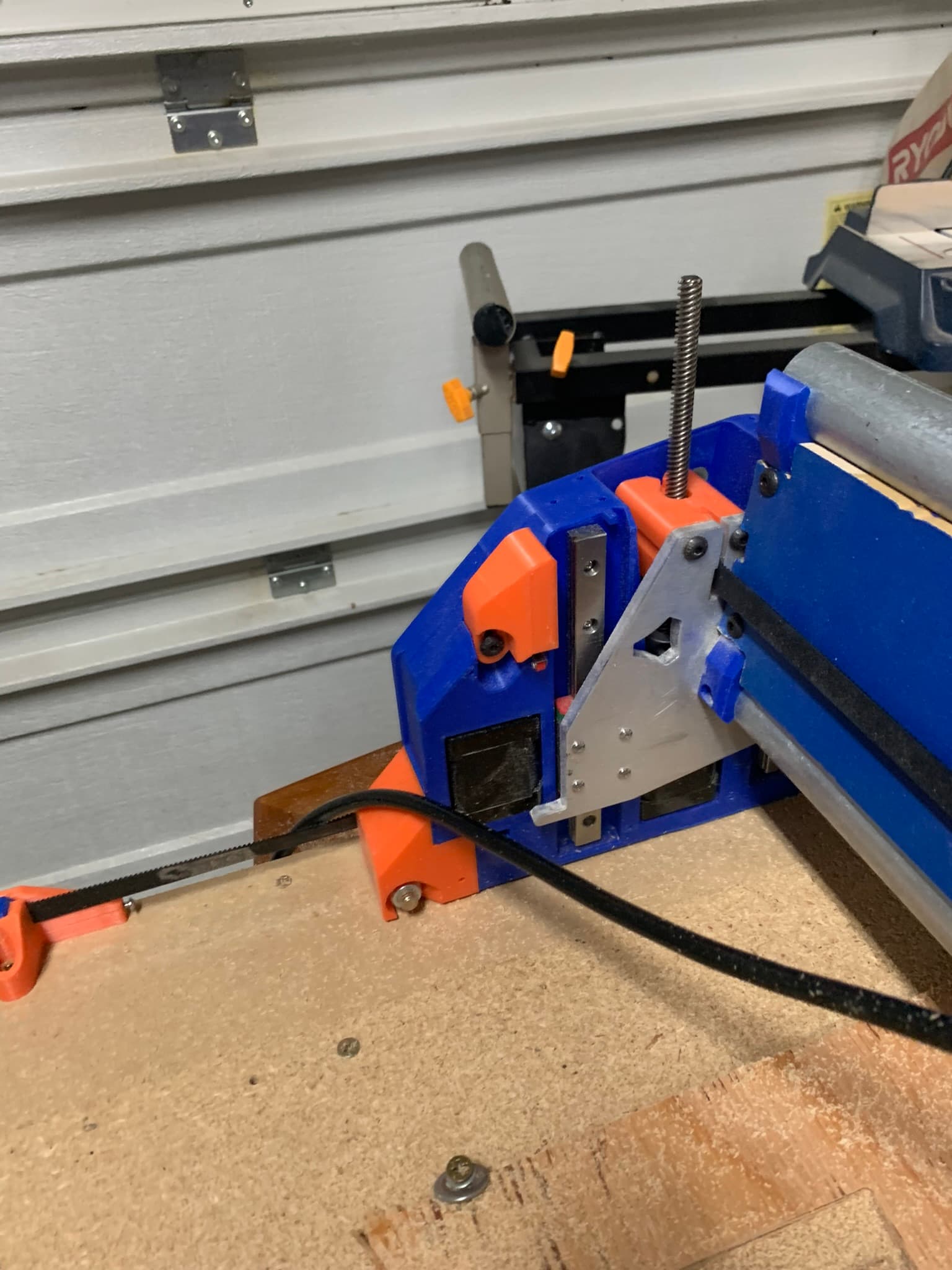
Thickness of the belt (2.43 mm). Note from previous post that width of milled cut in the aluminum plate was 2.07 mm. This was not only a problem for the X-min, but also for each of the Y-max printed pieces.
Remember I said I was building a full-sheet machine but decided to cut the Y axis short for now? That was fun trying to learn to “tile” the strut plates for a smaller work area than the struts.
Youtube to the rescue.
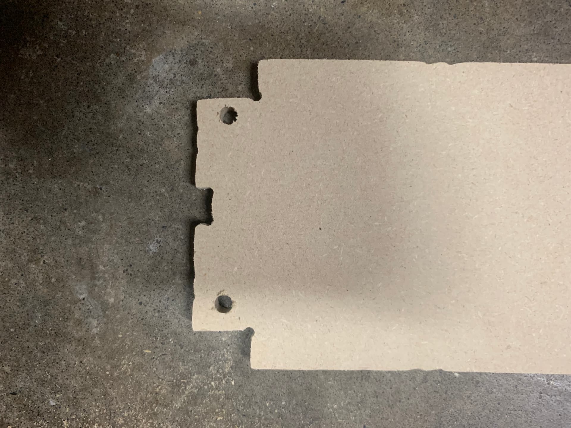
Machine the bottom two alignment holes into the spoil board
Machine those same two alignment holes and the upper alignment holes into the work-piece
Machine the lower half of the part
Slide the workpiece down and insert dowels into the upper alignment holes
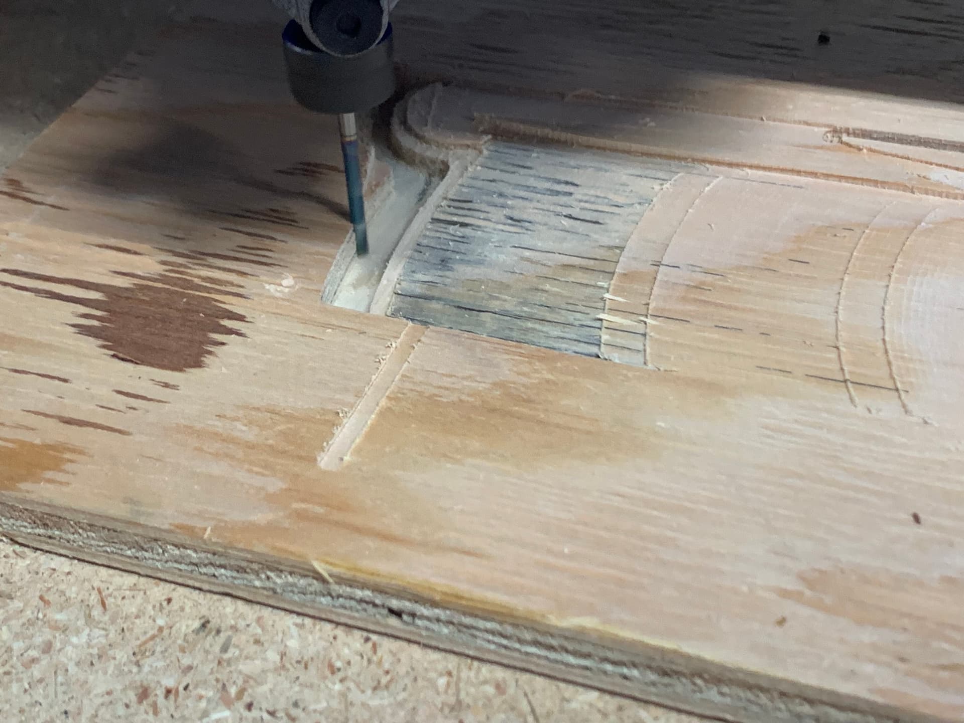
My thinking was that the Z lead screws are not lubed and it is skipping steps or binding while trying to raise Z. This was supposed to be a pocket toolpath at a single depth.
You can clearly see as the tool progressed from right to left each time the Z axis fell a bit further after a retract.
Yeah, don’t do that.
Noise immunity on an endstop switch is pretty much not an issue with these machines.
Pay careful attention to this, the strut plate is the secret to the LowRider rigidity. You may want to cut a better set when the machine is assembled. I also like to paint the MDF with wood glue. Doing that seals it and adds just a bit of strength.
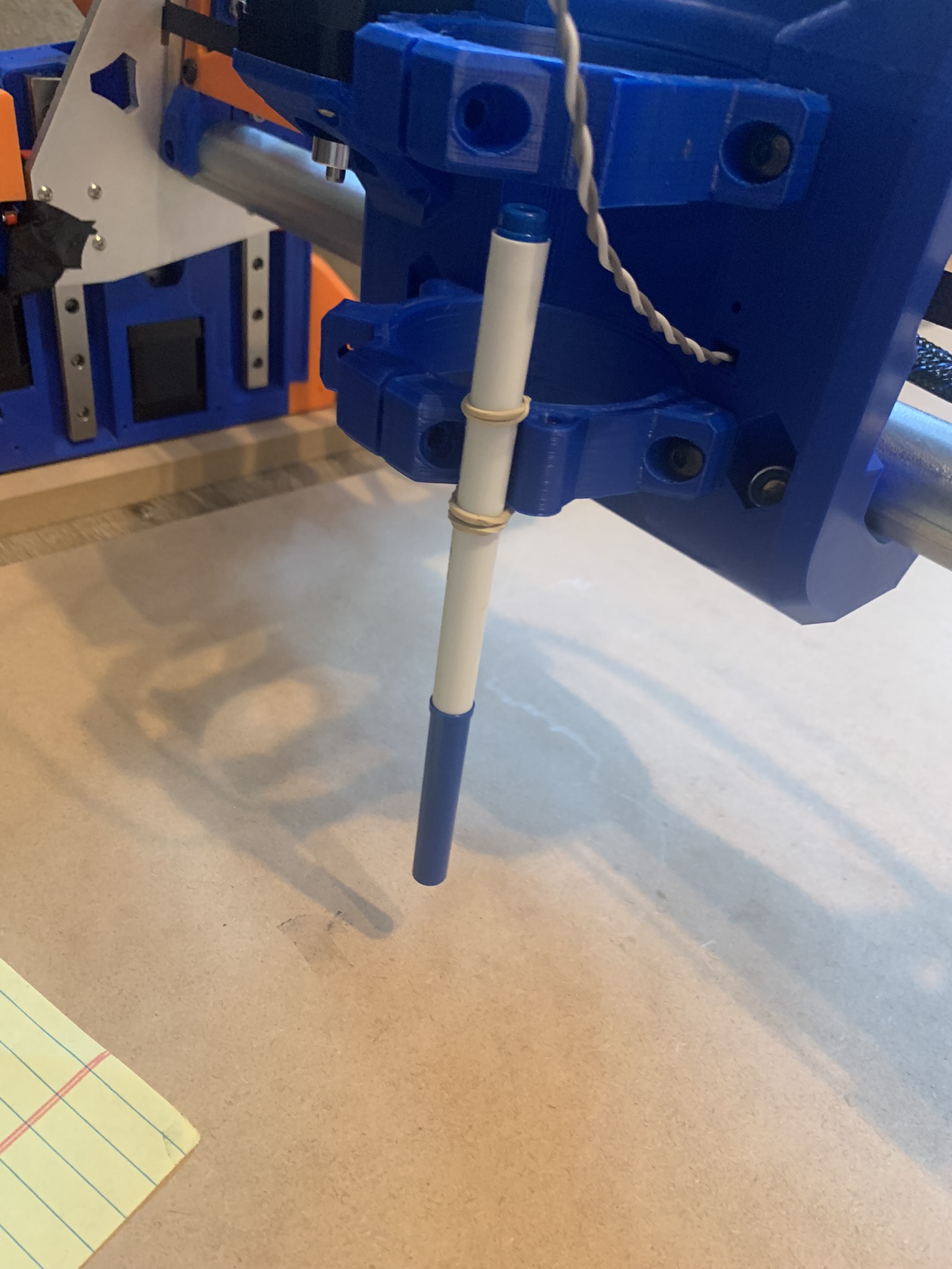
Yep, make sure you lube those lead screws. Also be sure the Z stubs are properly aligned and you don’t have the long cross screws installed.
What happened there? Do you have dust collection? Is it grounded?
I saw someone use a string and a vacuum to get a line through a conduit for pulling cable. Wondering if the same might work so these wires could be pulled instead of trying to push them.
Pay careful attention to this, the strut plate is the secret to the LowRider rigidity. You may want to cut a better set when the machine is assembled. I also like to paint the MDF with wood glue. Doing that seals it and adds just a bit of strength.
That is a great idea - may also explain the binding on the X-axis in some spots and grinding noises from the core being too loose in others..
What happened there? Do you have dust collection? Is it grounded?
No dust collection yet. Why do you ask? I’ve seen the posts on static discharge from the dust collector hoses/bins. Is that an issue on shop vacs too?
What is the required maintenance like for these machines? Do the skateboard bearings need cleaning?
I built one of the LR4 beta builds that I did with a hand-cut strut plate. It was a miserable experience. I then 3d printed a set of temporary strut plates and cut a real strut plate with those. Same exact beam, just replacing the crappy strut plate with a well made one changed that machine from crappy to awesome.
Depends really on your environment. If it’s humid and you never get a zap when handling shop vac hoses or buckets, then don’t worry about it. If you ever do get zapped, then consider that you’re also zapping your machine.
I’m sure at some point they need work, but I just blow things off with an air gun. The recommended bearings are the RS (sealed) ones, and I’ve not had any issues with those. If it were an open ZZ style bearing then I’d worry about them.
Stubs or nuts? On one of the first cuts after reassembling with the strut plate, the left side nut (bottom piece) was not aligned with the stub (top piece). I fixed that & still had the issue with left Z dropping..
If it’s binding in the right “resistance”, it will effectively “drop” due to losing steps on the upwards movement, which would be consistent with the images further up.
5mm/s should be plenty slow. Make sure you have plenty of lube on your lead screws. That can cause problems for sure. Maybe post a video if you haven’t already, I didn’t go back through all the past post.
I didn’t have lube - I know & will fix that for next try..
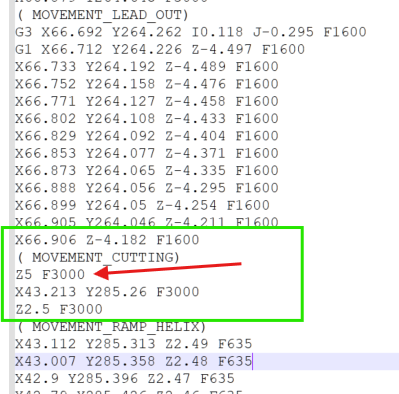
This looks concerning to me (if I’m reading it correctly):
– Move from Z-4.182 to Z5 at 3000 mm/min?
Post-Processor bug? I see a Z move at 50m/s. I’m sure that’s my fault in the CAM but doesn’t the Post-Processor limit speeds?
%
(Fusion CAM 2604.1.25)
( Posts processor: MPCNC v3.0 Beta 3.cps)
( Gcode generated: Monday, October 13, 2025 1:23:32 AM GMT)
( Document: sign_back)
( Setup: Setup2)
(When using Fusion for Personal Use, the feedrate of rapid)
(moves is reduced to match the feedrate of cutting moves,)
(which can increase machining time. Unrestricted rapid moves)
(are available with a Fusion Subscription.)
( )
( Ranges Table:)
( X: Min=38.678 Max=322.821 Size=284.143)
( Y: Min=150.41 Max=719.856 Size=569.446)
( Z: Min=-4.5 Max=10 Size=14.5)
( )
( Tools Table:)
( T1 D=3.175 CR=0 - ZMIN=-4.5 - flat end mill )
( )
( Feedrate and Scaling Properties:)
( Feed: Travel speed X/Y = 2500)
( Feed: Travel Speed Z = 300)
( Feed: Enforce Feedrate = true)
( Feed: Scale Feedrate = false)
( Feed: Max XY Cut Speed = 900)
( Feed: Max Z Cut Speed = 180)
( Feed: Max Toolpath Speed = 1000)
( )
( G1->G0 Mapping Properties:)
( Map: First G1 → G0 Rapid = false)
( Map: G1s → G0 Rapids = false)
( Map: SafeZ Mode = Retract : default = 15)
( Map: Allow Rapid Z = true)
( )
Lube is 100% needed. If you got your kit from V1 it came with a small thing of lube.
50mm/s rapid is WAY too fast for sure. Even if it was lubed you would most likely skip steps there. I am guessing you aren’t using Estlcam? If you are that is an easy fix, if you are using something else then I’m not sure how you would fix it.