First time setting up MPCNC. Initially setup and ran a movement test. Y axis worked perfectly. X axis on the otherhand sounds like an angry bee in a jar and a whole lot of vibration.
I noticed the squaring of the trucks were off by a lot since initially squaring them. I tore it all down and setup it again loosening the trucks and re-squaring. I tried it again and now both sound like angry bees and chatter in both x and y.
Any help would be appreciated. I squared the whole thing, loosened belts, loosened truck bolts, tightened them both ways. I really have tried everything.
The angry bee sound is almost always the steppers losing steps. When the stepper fails to move forward in one step, it will spin around almost 360 degrees on the next step causing the noise. There are a lot of possible reasons for lost steps. Here are some things to check:
Make sure you can easily slide the axes when the power is off. If an axis is binding, the steppers will lose steps.
Check the grub screws that hold the pulleys to the stepper motors. If one on an axis is not tight, that end will slip and axis will bind.
Verify that both steppers are being driven. With the power on, move both axes slightly using the electronics, then, with the power still on, verify that both stepper motors are engaged. If you can easily move either end, then that stepper is not engaged and the axis will bind during movement. This happens when the wrong firmware is installed, but there are other possible reasons.
There are other less likely possibilities. Current set too low on the stepper drivers for example, or intermittent wiring issues.
Just to reiterate: do NOT plug in or disconnect motors while your board is powered during troubleshooting! It is a very good and valuable thing to remember
Made sure everything moves easily. Did this multiple times.
Checked grub screws. All tight.
Steppers still have both axis (x,y) 1 of each side disengaging. I updated the firmware using platformIO with the dual endstop firmware. Everything said it was updated and sent but still 1 stepper for both x and y doesn’t have load to it.
I have not checked the current on the stepper drivers. I have wired everything like the instructions with the wiring kit. Nothing has been modified.
zen_patrick: Thank you for the tips. I have followed that to a T.
Is the X2 and Y2 steppers not working at all, or does it disengage during use?
Are you still losing steps?
Do you see Dual on the splash screen?
What control board are you using?
You will only have to check the driver current if you are using DRV8825 or A4988 drivers. Most other drivers using control boards for the MPCNC set the current in the firmware rather than a potentiometer on the stepper driver.
It’s the X2 and Y2. Those are the loose steppers. I don’t think it’s losing steps. One takes off and then the other catches up. I plugged in the LCD screen and it’s blank.
Given that the second stepper is loose, the most likely problem is that the second motor is not being energized at all. The second one “catches up” because it is being dragged along with the first motor. The following can cause that problem:
Issue with the wiring
Bad stepper driver
Stepper driver having the current set too low
Wrong firmware
Theoretically the problem could be a bad stepper motor, but that is exceedingly unlikely.
You can troubleshoot to identify which one is the problem.
Swap the stepper wiring at the control board between X1/X2 Y1/Y2. If the problem remains with the second stepper motor, then you have a wiring issue.
Send an M115 to your control board from RepetierHost and look at the response. This should tell you what firmware you are using. You are looking for “Dual” in the version.
If you are using DRV8825 or A4988 drivers, then you must check the current. There are a number of tutorials on the internet on how to set the current for these drivers. It is a matter of setting the correct v-v-ref voltage. The v-ref calculation is different between the two drivers.
Assuming all the above check out, then you can check for a bad driver by switching the drivers between X1/X2 and Y1/Y2.
Note that unplugging a stepper while it is energized will often toast a stepper driver.
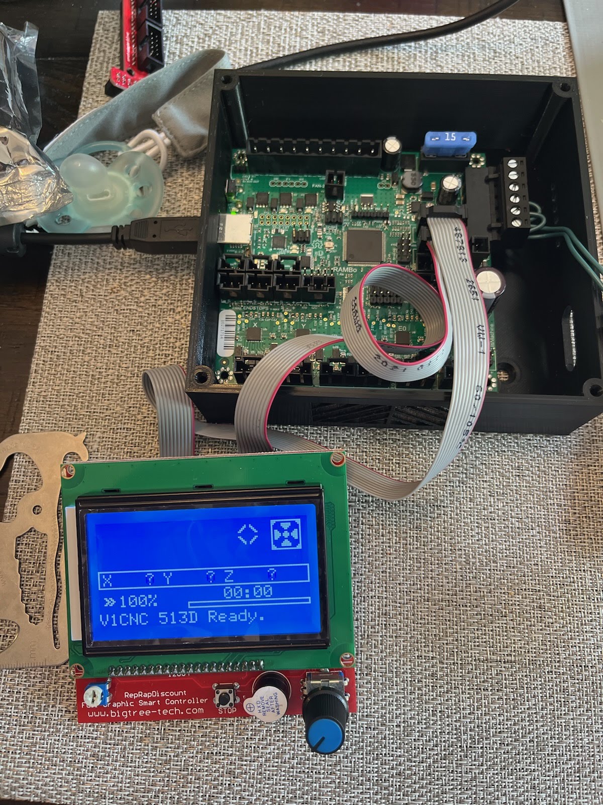
As for your screen, if you are running a smart controller like this one, don’t assume any diagram is correct and try all combinations of both plugs and rotations of the two cables. You may have to trim the “key” on the cable to rotate the connection. Also make sure you check the various brightness settings using the potentiometer in the lower left of the display at each cable configuration.
If you are running a TFT35 display, be aware that there are three separate cables that must be connected.
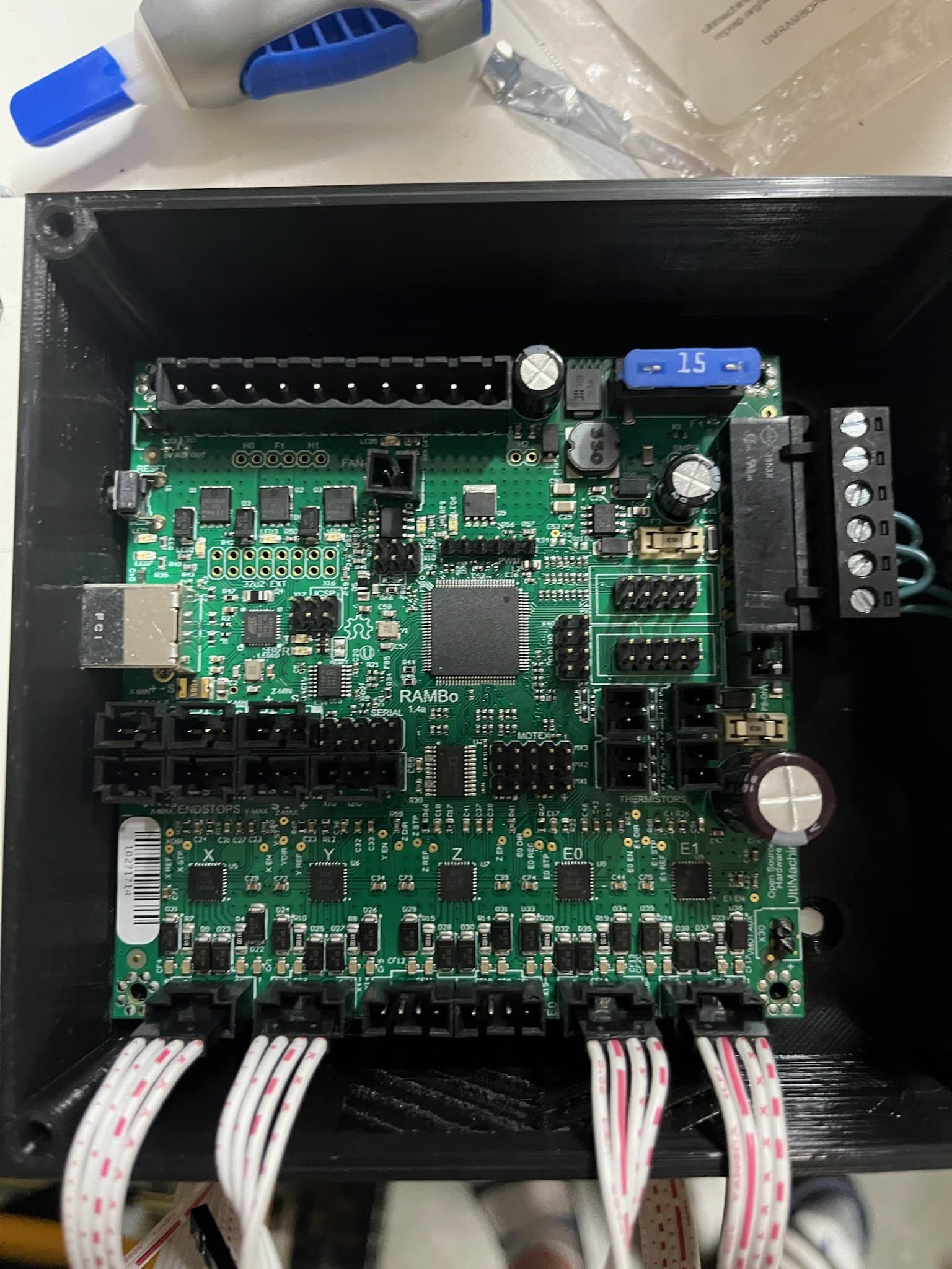
Posting a picture of your control board might help us spot issues.
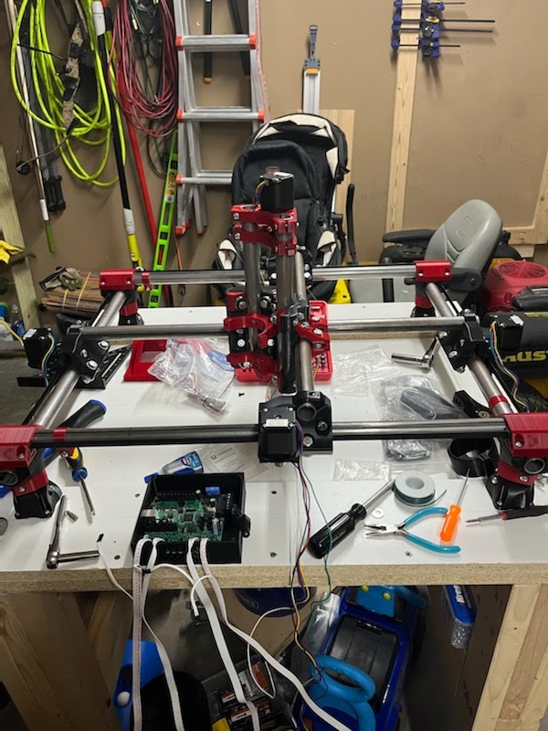
Here is some of my wiring setup. I just got the LCD to work.
It’s showing 513D. Not sure what that is, since I just reflashed last night. The firmware didn’t work it seems.
How do I send a M115? I’ve googled it so much and can’t seem to find it?
The wiring harness’ are setup according to the picture:
X1 = front X stepper
Y1 = left Y stepper
X2/E0 = back X stepper
Y2/E1 = right Y stepper
First, the 513D version is the latest dual firmware and what you should have on your board, so, unless you made changes to the firmware, your issues are not related to the version of the firmware. The ‘D’ in the version number displayed on the screen stands for ‘Dual.’ Second, for the Rambo board, the stepper current is set in the firmware, so the current is correct and does not need to be adjusted by you.
Now that you have the screen working, what I want you to do is 1) start up the control board, 2) using the screen move both X and Y by just 1mm, then 3) check both ends of each axis to see what steppers are engaged. The menus are not very intuitive on the display wrt movement. You don’t want to home the axes, just move them a tiny amount. After the first movement on any axis, the steppers should be engaged, and it should be difficult to move the axes on both ends. The nature of your problem will be different if only one end is engaged vs. both ends engaged.
If only one end is engaged, you are down to bad wiring, bad stepper driver, or bad steppers. Of the 100s (1000s ?) of issues I’ve seen concerning Rambo boards wrt steppers, I’ve only seen one instance of a bad driver right out of the box…and that was on board purchased from Aliexpress and therefore may have been some sort of clone or reject board. I’m not sure I’ve ever seen a bad stepper motor on the forum. You can collect more data to narrow the problem down by rerunning the above movement test and by swapping the wiring first at the control board end and second at the stepper end. This all assumes the issue is that one of the pair of steppers is not engaging. If you have a multi-meter, running a continuity test on all the wiring to the second motor might spot the problem.
How do I send a M115?
If you are using RepetierHost, under the Manual Control tab, there is the following field that can be used to send g-code to your control board.
Most other sending software also have a way to send manual commands. For the display, you can put g-code in a file and run them.
You have helped tremendously! I went through and did a continuity check on all wires. Went to check each axis and movement and finally saw one side worked (x axis). The y axis didn’t work. I turned it off and switched the plugs around to check and when I did that the y axis didn’t chatter like the other times, but the x axis chattered. The y axis was backwards at that point.
From all this I realized the plugs to the board don’t sit correctly. So I plugged them in and taped them to the table so they wouldn’t move. They were then straight up and down to the board. This seemed to be the problem the whole time.
I will have to find the right connector to plug the steppers into the board.
Again thank you for all your help on this. I really appreciate it.
I have made tremendous experience using a drop of hot glue on the side of the plug after it has been plugged in and checked… When the hotglue is really hot it pulls itself between plug and socket and creates a tight connection. Then you don‘t need to change plugs. It secures also fairly well against vibrations, should you keep the board on the machine. I used this on my ZenXY build to make sure I hopefully never have to dig into the control box again
Keep in mind that unplugging these plugs later is still possible, but not as easy. Should you experiment a lot etc this might not be suitable for you.