I’m doing it more for a learning experience than anything. I’m a big Linux user. It’s helping me get under the hood of motion control. There is potential for a 4th axis. Practical? Who knows, but possible.
I had gotten then new A4988s, extra in case I blow these up, and have them plugged in and wiring. So far, so good. no overheating with some long gcode sessions. No load hooked into the motors yet. Took me a little while to decipher the Sainsmart version of the BOB, but got it figured out and am now blinking an LED with the spindle on code and turning off. That will be the signal for my IOT relay, which currently is using one of the fan pins on the Archim. I might have time this weekend to take it over to the MPCNC and give it a test drive. I am not quite sure about the Z stepper configuration. I think I have it now. It was spinning pretty fast, then I realized that I hadn’t switched the software config back to 1/16 microstepping. It was still on 32 from when I had the DRV8825s.
I have been reading up on the relay that is on the BOB. Lots of good discussion in the archives, including @jeffeb3’s thingiverse post on a four channel relay and Octoprint. I am not ready to mess with mains on a relay, but that post gave me an idea that I can control the 24v line power to the cncshield with the relay. Still a lot of reading to do before I attempt anything.
The breakout boards by Mesa Electronics are really popular with the linuxcnc guys right now. I’m a happy customer so far using this ethernet b.o.b. 7I96 picture
While I feel it’s very affordable it’s still more pricey than the route presented in the o.p.
[EDIT]
Apparently the SmoothStepper doesn’t work with linuxcnc.
While we’re on the subject here is short recent thread about a linuxcnc user converting from a parallel port to a mesa card. Ditching 25 pin bob - Page 2 - LinuxCNC
A typical mpcnc or lowrider runs at 2540 steps/inch, probably close enough to that 1000-2000 range. Food for thought…
I’m sticking with a parallel port BOB and cncshield. The angry pixies are something fierce in my shop and I don’t want to let them at the magic smoke on an expensive board.
I might be able to go live with a try on the MPCNC tomorrow. I have one dupont connector I need to redo. It was the first one I did and it’s a bit wonky and is giving intermittant issues on that axis.
Although there are quite a few LinuxCNC YouTube videos up, the vast majority are on just a few channels. I’ve been falling asleep at night listening to them.
Hi, I am a student of the Faculty of Engineering, Department of Mechanics. I have few skills in electronics. I want to know if it is possible to run Mach3 software with this interface and CNC Shield. If this is possible please I need a clear picture of the connections between all components (Interface, CNC Shield, Drivers, NEMA 17, and Power Supply). Hope you can help me.
I can’t speak directly to using this solution with Mach3, but years ago I used LinuxCNC to run a system based on the parallel port that was originally designed to use Mach3, and it was very straightforward to adjust between the two if you knew what LPT connector, which is almost always printed right on the break-out-board (BoB) component, is carrying the signal (enable, step, or direction) for each axis that you will hook a particular pin on the CNC shield. You may also want to connect up “extra” pins if you’ve got options for spindle (on/off, speed, direction) and relays (e.g. coolant flood or mist are common).
It appears you’ll want to connect the appropriate break-out-board pins to the CNC shield pins for a common enable signal (shared between all axes, based on notes from the postings above) and then per-axis step and direction pins, which you can re-map in the software as needed. I’d suggest checking the software mappings first and wiring up to match the defaults as much as possible. Since you have flexibility in the wiring, why force yourself to make changes in the software too?
It may sound easy for me to say, having done something this before, but I think everything you need is already in this discussion thread.
Computer LPT/printer port connects to break-out board with parallel cable - make sure you get one with all the wires - there are serial cables that look very similar but only have 4 or 5 conductors in them which isn’t enough for the needs of this project.
The break out board connects to CNC shield, but you have to match the pins the way you want them per axis.
Motor power supply connects to CNC shield screw terminals.
CNC shield will also need 5v for some TTL, which it can get from a USB connection, a separate 5v “wall wart” transformer or a dc-dc “buck” converter.
Stepper motors connect to the pre-labeled connectors on the CNC shield.
Don’t hesitate to come back with any questions. This forum is full of really helpful people.
I’ve never personally used Mach3 for any of my parallel port-driven machines… only LinuxCNC. IIRC however, Mach3 has its “roots” in LinuxCNC, aka EMC/EMC2. I suspect Mach3 would have no trouble playing through this interface… as long as you configure the PC’s parallel port properly.
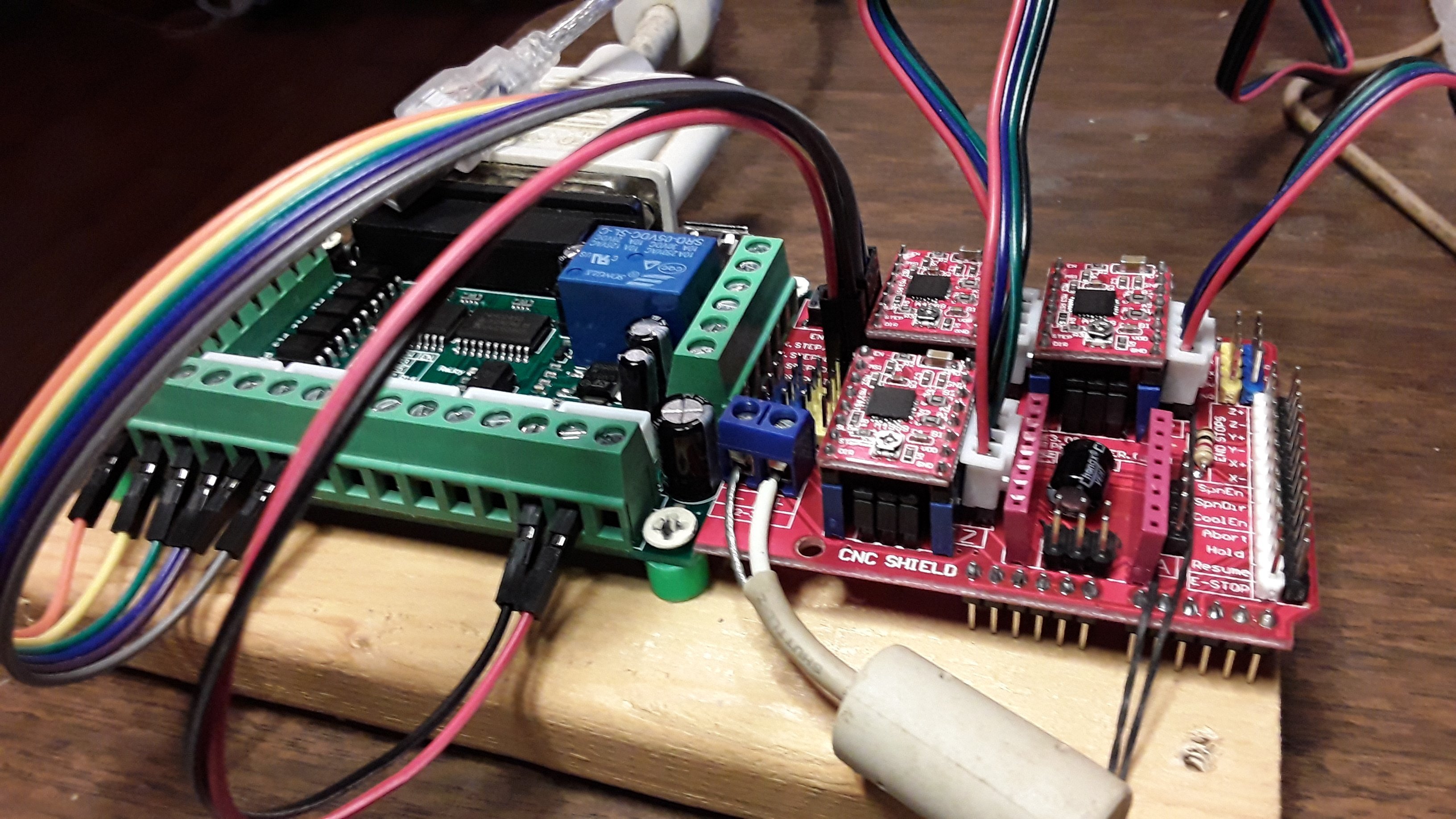
That said, the interface I show here is very basic… just a simple 3-axis motion controller. The breakout board (BOB) breaks out all the parallel port signals, of course… I only used the ones I needed. I never generated a schematic as the hookup was extremely simple. This photo really shows enough detail you shouldn’t have too much trouble creating a schematic…
Note the parallel and USB cables at the rear, connected to the BOB. The USB cable supplies only +5 volts to the BOB… no data. All the LinuxCNC (Mach3) step and direction signals for X/Y/Z control come to the BOB from the PC’s parallel port and the group of six wires (far left) are X step and direction, Y step and direction, and Z step and direction… going to the CNC shield (without the Arduino Uno). In this case, the CNC shield is just being used as a breadboard for mounting and connecting the A4988 step-stick driver modules. The red/black pair of wires (lower center) feed +5 volts to the logic section of the A4988’s. The white coax cable (center) is the +12 volt stepper motor power to the shield. And, finally, the three four-wire bundles (upper right) coming off the shield go to the NEMA 17 bipolar motors.
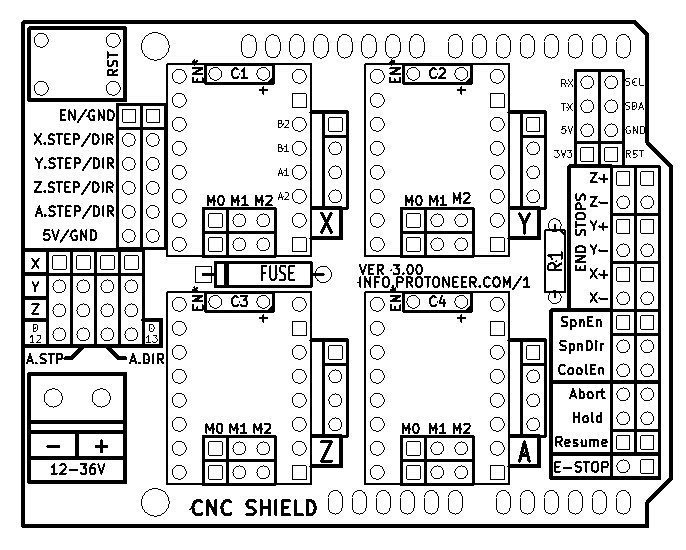
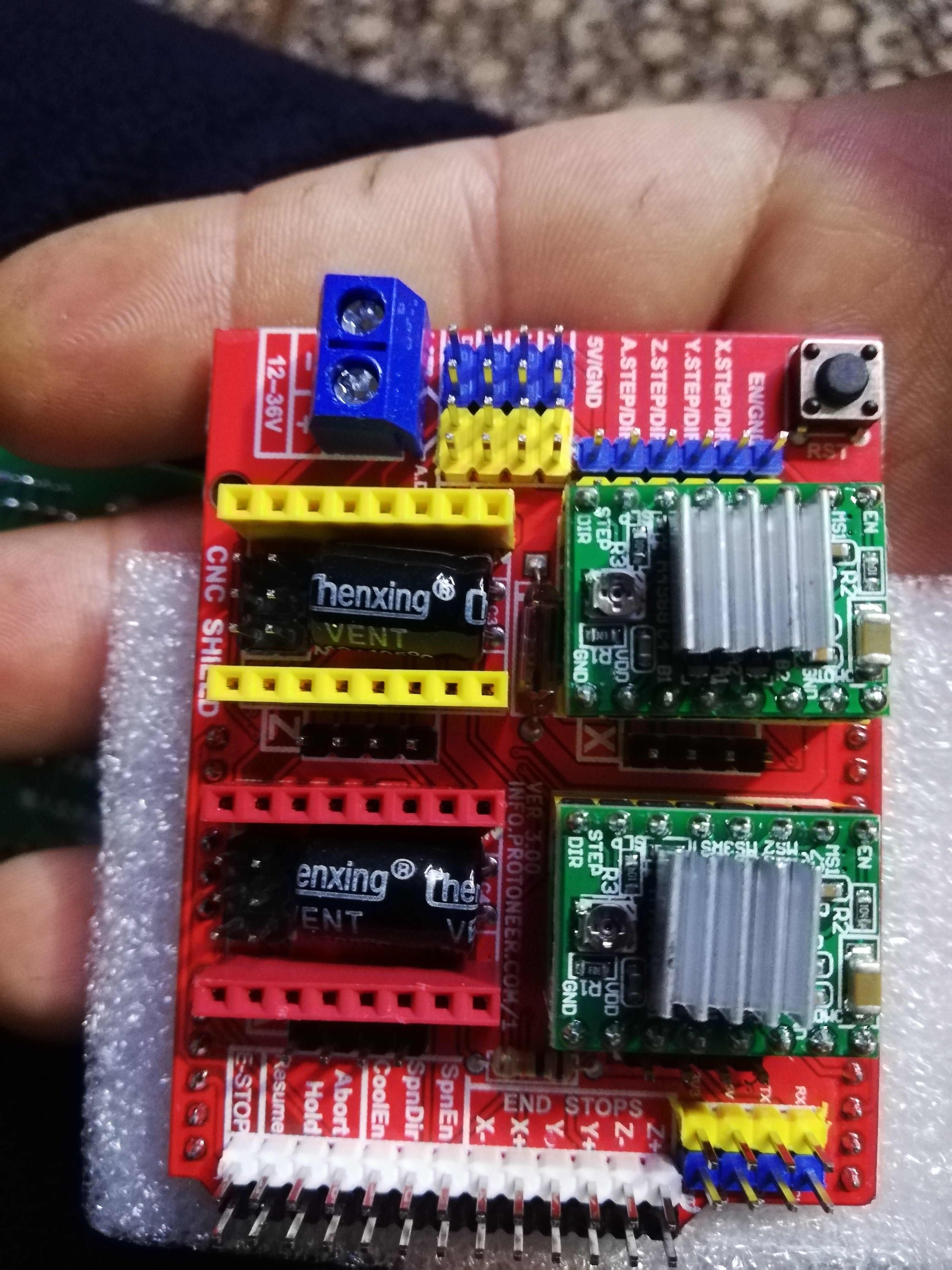
Note the CNC Shield diagram below…
All the X/Y/Z step and direction wires from BOB connect to the respective pins grouped in the upper left area of the shield, below the reset switch. The two wires from BOB carrying +5 volts connect to the “5V/GND” pair of pins in that same group. The “EN/GND” pair of pins get a jumper to enable all the stepper driver modules.
Again, this provides simple 3-axis control for a basic CNC machine… nothing more.
Hello my friend, I hope you are fine, my friend. I have a panel mach3 and a cnc a4988 shield. I want to connect it as it did, but I could not understand the delivery method because of the difference in yields. So, I ask you, my dear friend, to send me the connection diagram between the two panels if possible. Part of the photovoltaic production line I would be very ripe for you
I have given you the wiring on your other posting Qasim
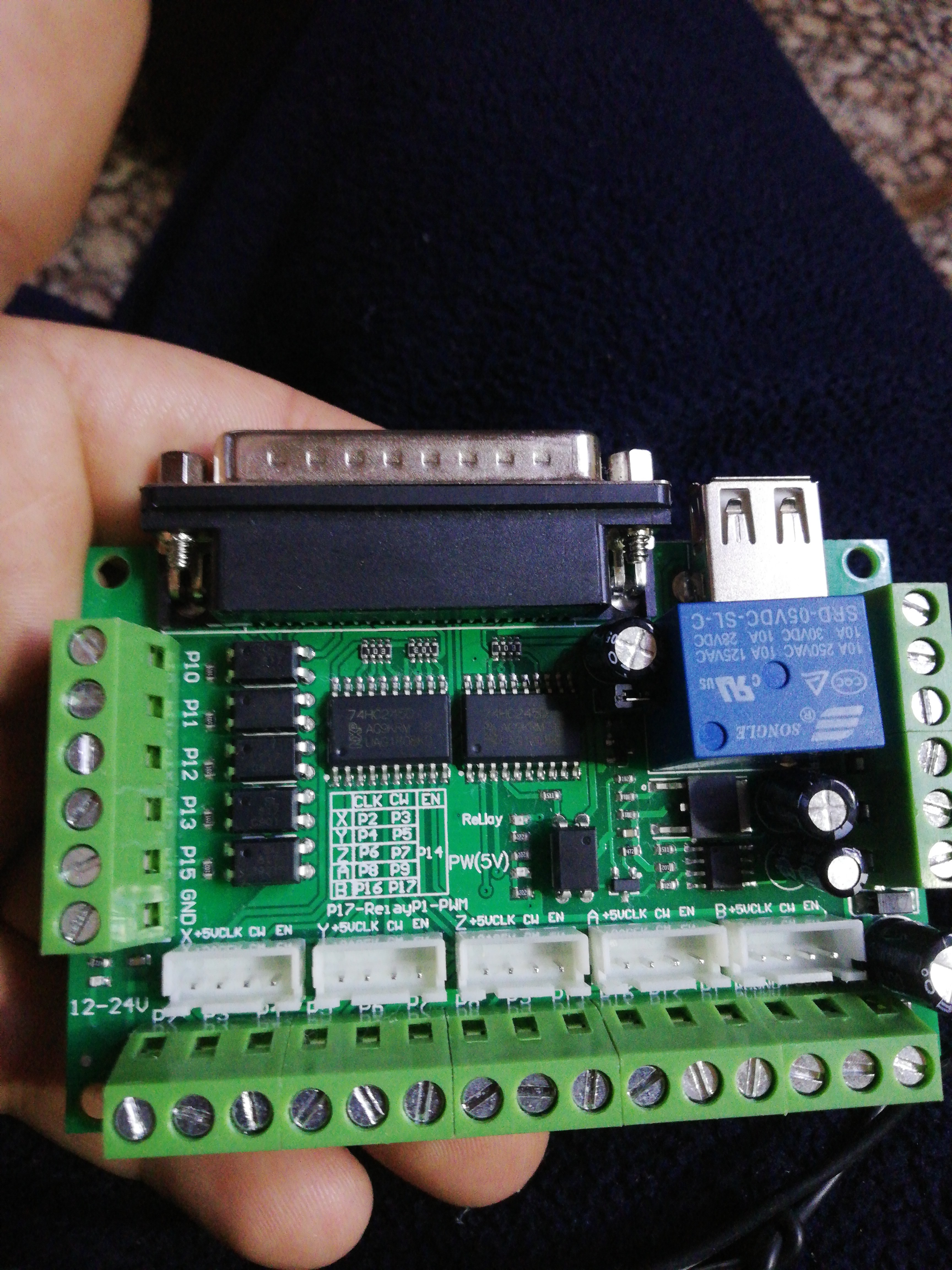
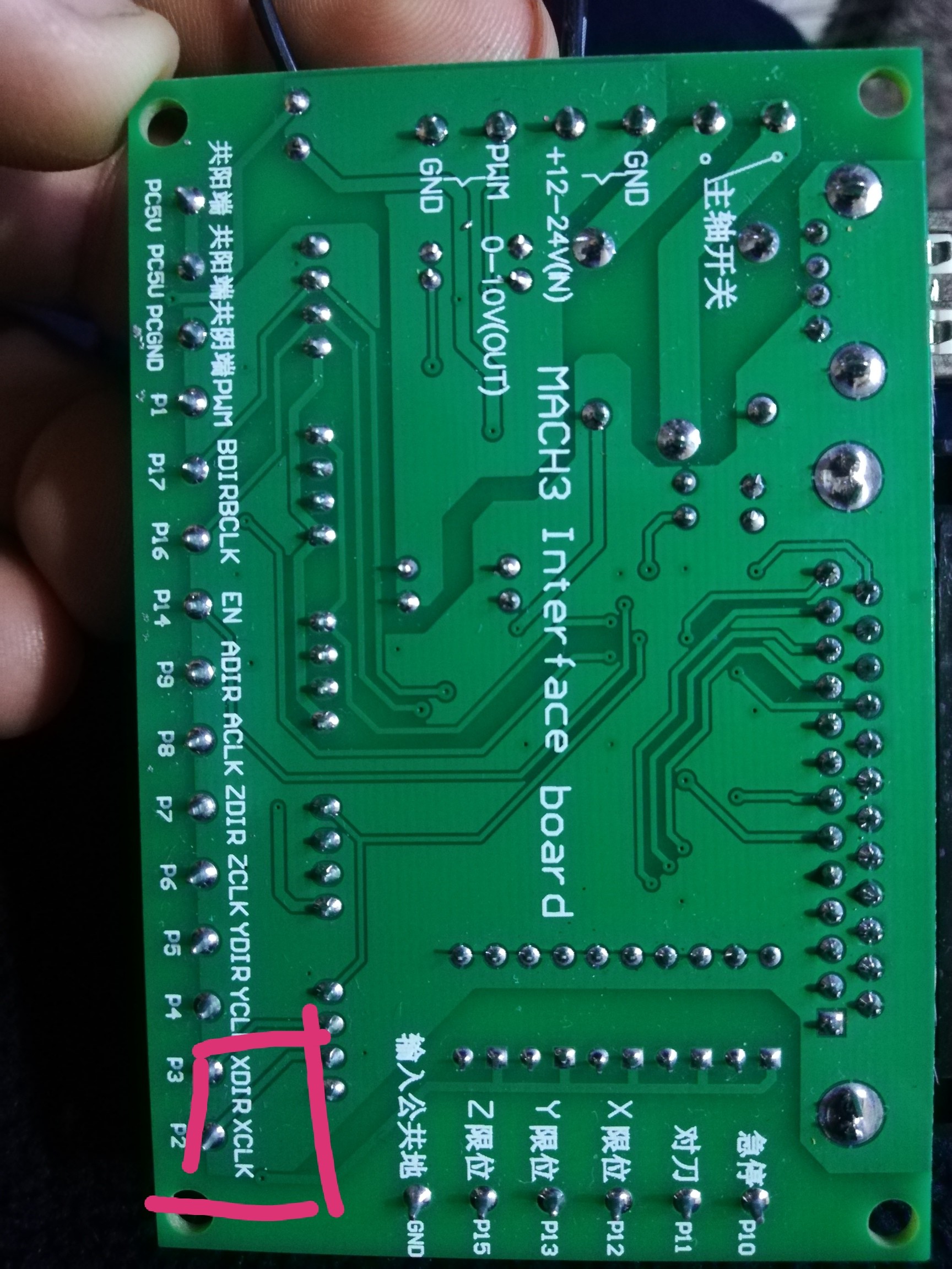
XP to X STEP
XD to X DIR
YP to Y STEP
YD to Y DIR
ZP to Z STEP
ZD to Z DIR
Connect ENABLE, MS1, MS2 and MS3 to VDD on the A4988. connect SLEEP to RESET, connect the stepper motor to 1A, 1B, 2A and 2B, connect your 8 to 35V supply to VMOT and GND and a 5V supply to VDD and GND as per this diagram.
After some long time I finally got my MPCNC working with LinuxCNC (I’ve only done some air milling for testing).
I really like it so far and I think it’s a really good alternative to the 3D printer boards people are using.
I got a cheap Chinese 5 axis breakout board hooked up to a cheap Dell Optiplex 780 with a Core2Duo E8500 processor. For the drivers I have 5 Leadshine DM542’s set to 1/8 microstepping… I prefer more torque over the 1/16 or 1/32 microsteps… which is not needed for CNC right?
The drivers where ‘expensive,’ but you can use anything you like and make it a really cheap set-up… as cheap or cheaper than a 3D printer board.
What I really like is it’s so flexible… the breakout board is just some kind of translation of your DB25 cable. It’s got a couple of outputs and inputs and you can set it up how ever you like. You can even hook up a second breakout board if you need more inputs or outputs. The stepconf wizard is easy, but you need some hand editing later… which is also pretty easy once you understand it. I also never worked with Linux (Debian) before, but that’s also pretty easy, you just need to know the basics. I only spend a long time figuring out how to install a package which contained my WiFi drivers
What I like about LinuxCNC is it’s a real CNC program and you can adjust and add anything you can dream off…and if you want you to upgrade to a more professional machine you can still use LinuxCNC. I hooked up a Xbox 360 controller to it and with HAL and some programing you can make LinuxCNC do anything.
On the X, Y and Z-axis I set up homing switches and in LinuxCNC I configured soft limits. So the machine won’t even let me crash it
And the funny thing is… I only needed 2 inputs for all the 5 homing switches (X1 + X2 and Y1 + Y2 needs to be on a different input)… But if you want to be really fast you can home all axis at the same time… but then you will need 5 inputs…
And my Makita spindle starts automatically through a relay when the program starts or via a M3 command. Also easy to set-up, just hook the relay up to an output pin and assign it in the stepconf wizzard…
Another advantage is the ability to set a home offset… so if you want to square your gantry and the, for example, X1 and X2 home switches are located a bit different from each other, you can correct this in the software if you want. So it homes and X1 or X2 and backs off the value you set in the home offset… really handy!
If some one is interested I can share my wiring and give some tips how to set LinuxCNC up…


 But if you want to be really fast you can home all axis at the same time… but then you will need 5 inputs…