MakerHawk 6pcs Optical Endstop with 1M cable Optical Switch Sensor Photoelectric Light Control Optical Limit Switch Module for 3D Printer
About this item
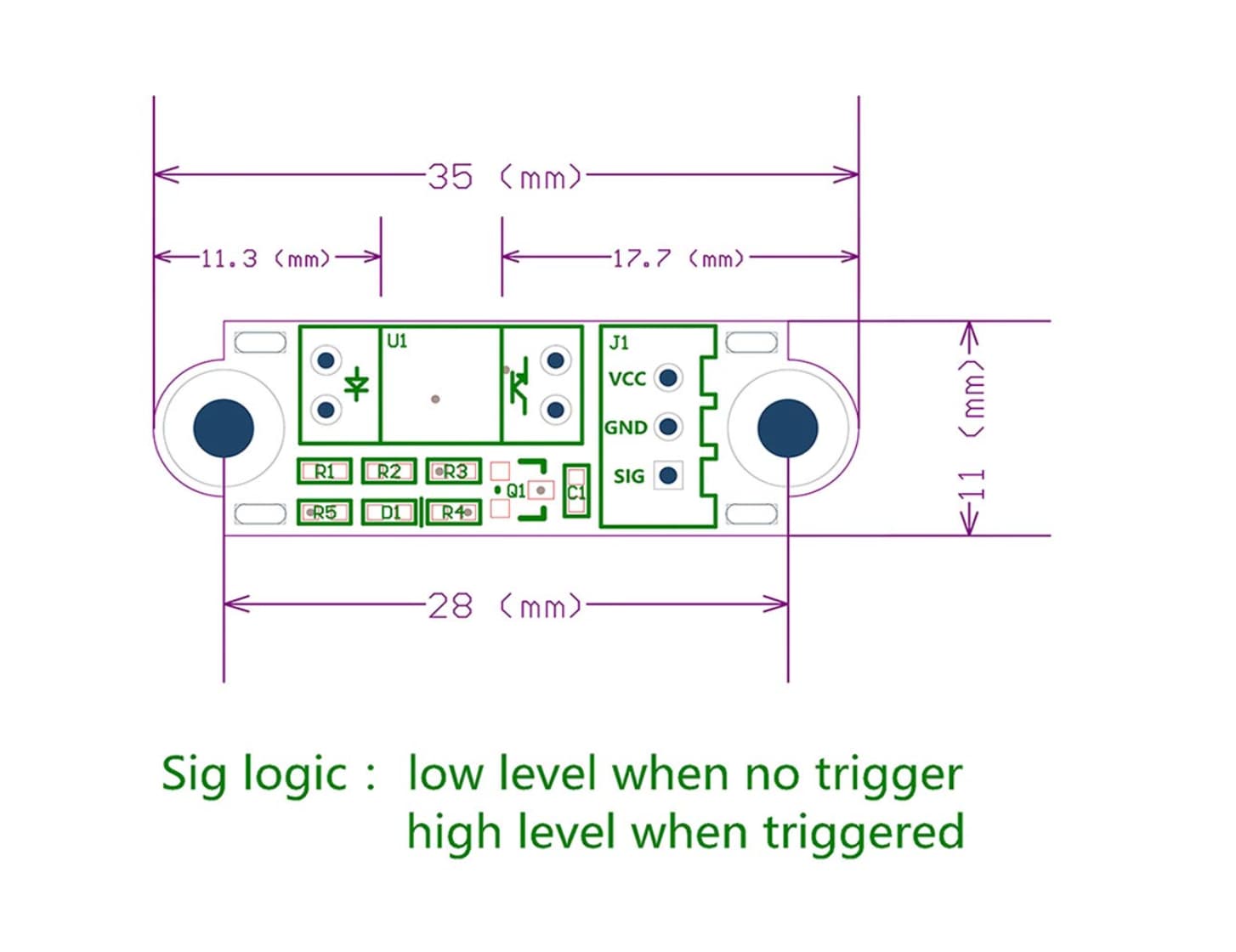
VCC: 2.7V to 5V.
The trigger is sensitive and quiet.
With high repeatability and no mechanical collision.
Using optically transmissive principles of design, no loss, no noise with a longer life.
SIG logic: output low level when there is no trigger and high level when there is trigger.How to trigger the photoelectric: Use the stopper to trigger the limit when it moves to the middle of the red contact groove (it is recommended not to use a transparent material stopper)
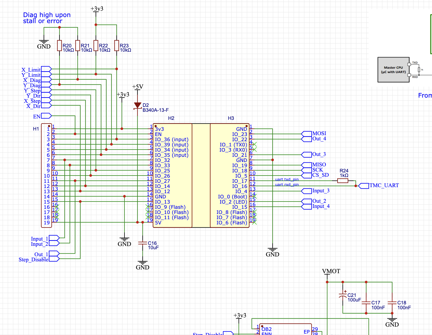
Looking at the schematics for the Bart Dring Pen/Laser board, the X and Y limit GPIO inputs are pulled up to +3.3V.
So, I wouldn’t hook these optical endstops directly up to +5V for Vcc. I don’t see a 3.3V output on any of the pen/laser connectors- so this needs a little thought. Perhaps a series resistor (something like 10K ohms) might work. I need to think about that.
For reference- this section of pen/laser schematic:
Honestly, I would just connect them to 5V. The “right” way to do it is to use a logic level converter. But in my experience, the esp is pretty robust to this kind of thing. If it were to put anything at risk, it would be the ESP, which is a pretty cheap part. I have enough on hand that I would risk the $5-10 ESP instead of buying some $5-10 logic level converters (until I killed one, then I would protect the second).
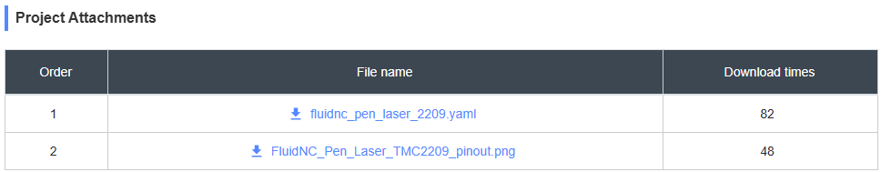
I have a slightly different board, but this is a link to an old config file. I have at least one update to make it home on boot, but that won’t affect you now:
Make sure you are paying attention and remember that yaml is for a dumb computer, so you have to be precise with the whitespace characters. I’m guessing you can merge an example config for that board with the settings I have on mine.
Nope. You’re going to have to try harder than that. I don’t have the right file for that board. You’re going to have to build it. That means reading the docs, unfortunately.
I’d connect the endstops Vcc to +5V (Maybe with a 1K series resistor), and then connect the signal pin to the endstop inputs through a 10K or maybe a 1K series current limiting resistor.
Less likely to blow up and ESP-32.
I don’t have anything to test with.
One of the things I’d like to have as an outcome here is to get the documentation pushed further forward.
I’ll work on that.
When I finish my LR3, one of the first projects after getting my repeat printer V5 side panels cut will be a ZenXY. When I do that, I’ll get Jackpot documentation put together as well.
We’ll get this current thread capped off with a working machine, then move on out from there.
I think @Ryan was talking about wanting to update the zen instructions for the jackpot, which would include a working config file. There was a step for the homing which recently got figured out on the rmrrf table.
Yes, when I build one up I’ll use jackpot and will document the configuration that works for me.
Understood.
That’s right, I’ll help sort that out in cooperation with @LosTyger .
Since I don’t have a pen/laser board, we’ll have to iterate on that with me reading the various pen laser board examples and then we’ll have to test and iterate that on that other setup.