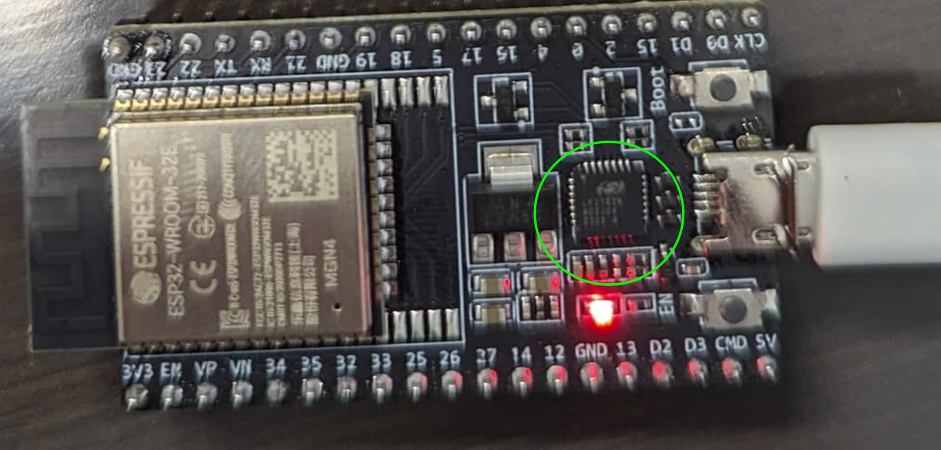
The easiest way is to first identify what chip you have on the ESP32. Tell us exactly what labeling on the USB/UART chip says. It will either be something like CH340 or CP-2102.
It’s the chip I’ve circled in your photograph from above.
I downloaded the universal driver, but I’m not sure what I need to do with it to install it. I guess I’m used to something with an auto-installer, but I’m not seeing anything like that.
Use the standard windows workflow. From device manager, click on the unidentified device. There’s options from there to pick the driver, point that to the location you unzipped the the driver to.
I’m on my MacBook and not near a windows machine to give you step-by-step instructions. Perhaps another community member will help you with that. Later this evening I may have a chance to get on a windows box and give you step-by-step.
What version of windows do you have (10 or 11? If Windows 10, is it 32 bit or 64 bit?)
Edit: also, you didn’t confirm that you have a CP201x chip. Please try to answer questions as we need those answers to help us help you.
Optical stops, or just microswitch endstops?
Optical endstops are a bit more tricky as they usually need power for the LEDs.
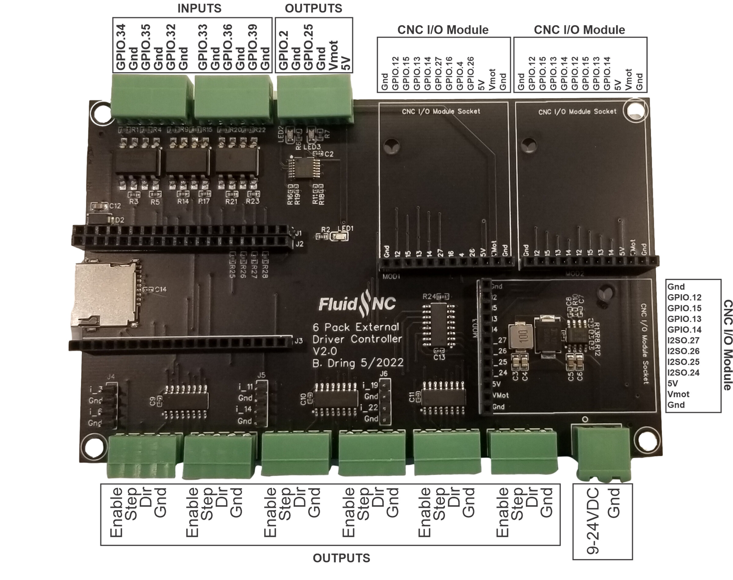
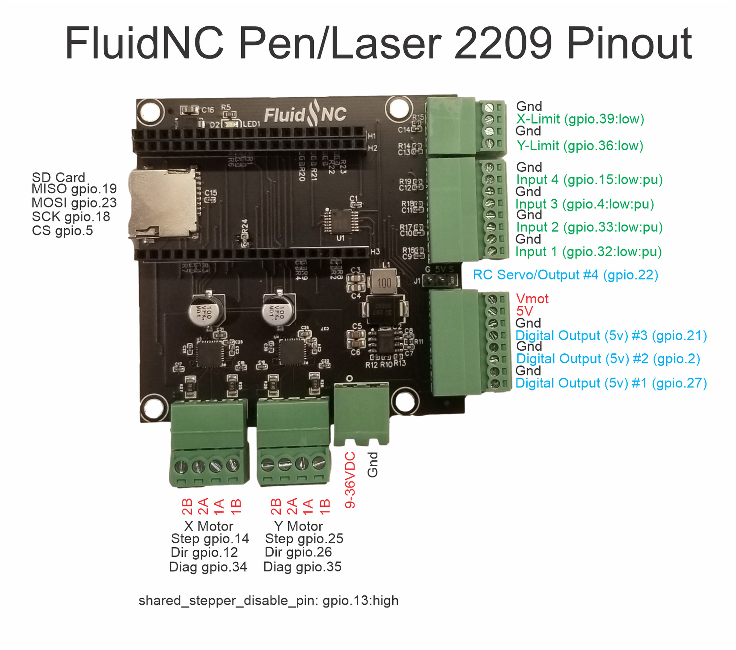
If they’re mechanical endstops, I’d suggest the GPIOs on the 6 pack. I’d start with the top left corner and work in. Don’t hook endstops up until we confirm how to connect them correctly to a 6-pack.
Also, which optical endstops are you using? Have a model, link, or picture?
As we figure this out for @LosTyger , we can use it to improve the documentation.
I checked the V1 store and there isn’t any data sheet or wiring data for the endstop that Ryan sells
It does note that VCC can be 2.7 up to 5V for that part, which is nice.
I would propose picking up 5V and Gnd from the output connector on Bart’s board , making a “Y” with ferrules so two wires would come from 5V and two wires from Gnd on the outputs connector.
I’d run separate wires for that 5V and GND individually over to each optical edstop VCC and Gnd.
The 3rd optical endstop pin on each endstop would then get run over to inputs. I’d use GPIO.34 for one endstop and GPIO.35 for the next.
To make any further progress on this, I need the data sheet for whatever optical endstop @LosTyger is using in the ZenXY build. That would allow me to confirm the notes above.
Definitely worth finding out the right info and updating the docs.
The reason I thought 3.3V might be better is I bet the optical endstop outputs Vcc. I’m not sure if the endstop pin on the jackpot is supposed to have 5V input. The esp is 3.3V. but it is pretty tough. I’m not sure if there is a resistor or other protection on the endstop input.