Hi all,
Again the docs don’t seem to have any info on this so I just have to guess, which risks frying my board with a short. The supplied limit switches from the shop have 3 contacts, but of course there are only 2 wires from them to the board. Can anyone explain which pins to use for which wiring endpoint in the board? I know they go to signal and ground on the board, and the docs say NC (Normally Closed) configuration, but that means nothing to me as I don’t know how that applies to a limit switch (again, I’m a noob to this but the docs seem to skip some of these quite important details). I have not seen it shown anywhere which contacts to use to connect to the limit switches themselves. If anyone knows, I’d appreciate it.
Thanks!
Matt
2 Likes
The end 2 (i.e. not the middle one) usually, but test with a meter
The docs show photos of the micro switches and their wiring - what else do you feel needs added?
1 Like
Thanks Dreyfus! I couldn’t find photos of the switches, so that was what I felt needs to be added.
If you have a link great, but if not, thank you for what you provided, it did the trick!
I checked these two links and several others that didn’t have any photos or description.
https://docs.v1e.com/electronics/ultimachine/#dual-end-stop_1
https://docs.v1e.com/electronics/dual-endstops/#basics
Best,
Matt
1 Like
These switches are almost always labeled:
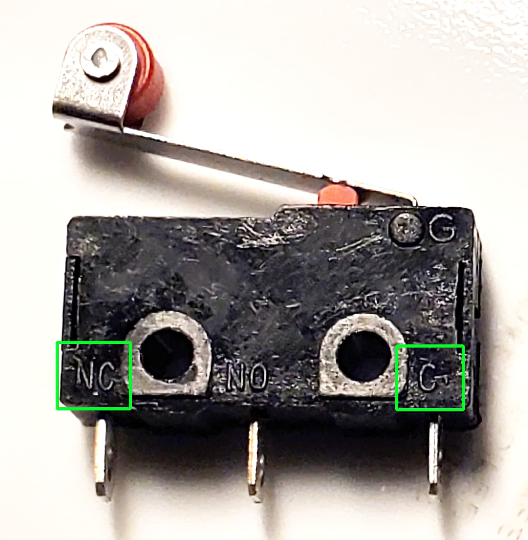
There will be a C or Com for the common terminal. NC is the normally closed pin, and the NO is the normally open pin. For this pictured switch, the outside two terminals are used (as indicated by Drefus). Polarity does not matter. You can connect these two pins to the S and GND pins of your control board in either order.
You can also test it with an ohmmeter. The two terminals that are connected when the switch is not pressed will be Com and NC.
Thanks Robert, that is very helpful as well! I tried looking for markings on the switches before installation but didn’t see any. It’s possible I missed them though. I appreciate the help and tolerance for a noob. I’m new to all this and I literally get like an hour per week work on this, so it’s slow going, especially if I have to go do research for many of the steps.
Your help is much appreciated!
Best,
Matt
1 Like
You can see the micro switches in this part of the build documentation and how they are wired
https://docs.v1e.com/lowrider/#side-plate-assemblies
Good luck with the rest of your build, I built mine the same way, a tiny bit at a time.

Thanks Dreyfus, very helpful. I’m building a regular MPCNC (Burly, that’s how long ago I started on this ![]() ), so I never looked at the Lowrider docs.
), so I never looked at the Lowrider docs.
The endstops are in now, just need to check square. Hopefully I’ll be making chips in a few weeks.
Appreciate the help!
Matt
Ah that’s my fault, sorry, I didn’t realise you weren’t making a LR. Well, you got what you need anyhow ![]()
thanks for bringing this up Matt, I was in the same shoes as you. Not knowing what to do next.
There are 3 pins, it depends on whether you want NC or NO. For most of them this is written down in tiny font on the switch. The two outside are NC what most people use.
close older topics to help with spambots, and faster new user questions.