Sorry, I was riding a car (coming home from Christmas vacation) while trying to read along, and I somehow missed this until now.
Homing to X-min and Y-max is indeed doable, albeit, the best way I know to do it, is by doing a logic swap in config, in which the X and Y labels / axes get swapped for each other.
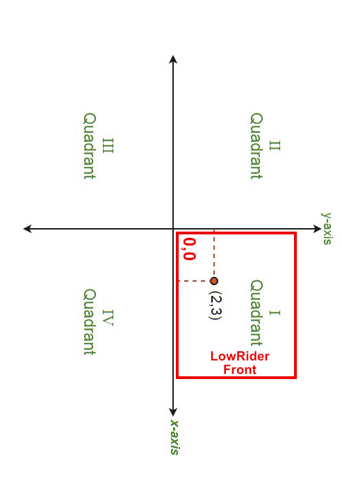
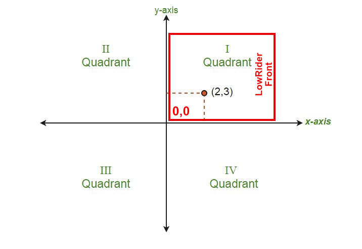
Thus your CAM work can still be done like normal, in the “quadrant 1” area where all your X and Y CAM coordinates are positive, is still on the table, just turned 90 degrees from “standard” LowRider, like this:
This kind of swap does not require any weird CAM magic or mumbo jumbo. The wide bottom edge of a landscape screen on a laptop or tablet during CAM work corresponds to the “wide” (long) side on the table. I personally have mine set up as “swapped” in this way, and I do prefer it. Obviously it is a departure from the standard plan.
I had another thought for how you could do homing to X-min and Y-max, without swapping the X and Y axes with each other (i.e. without rotating the coordinate system). Here’s the idea: for Y axis, edit the value named " mpos_mm – which according to the wiki …
mpos_mm – Sets the machine position after homing and limit switch pull-off in millimeters. If you want the machine position to be zero at the limit switch, set this to zero. Keep in mind the homing direction you choose this number.
So I think if you set it to 2270 (or something around that number as shown on your drawing), then when you home to that back left corner, it will home, then do the “pull_off”, and then set the Y axis location value to 2270, effectively setting the Y=0 to be a point at the front left of your table. !! At that point your X,Y nexus for 0,0 will be at the front left side (near left) of your table.
I think the mpos_mm value would be set to positive, but if I’m not understanding it right, then change it to a negative.
PS: also just to reitereate, I’m not 100% certain, but my current understanding of your setup is that your Y value is getting smaller as the machine moves toward the back, which means your Y stepper wires are plugged in backwards, and after you fix that, you’d need to edit your config for Y homing settings, changing positive_direction: false to true.
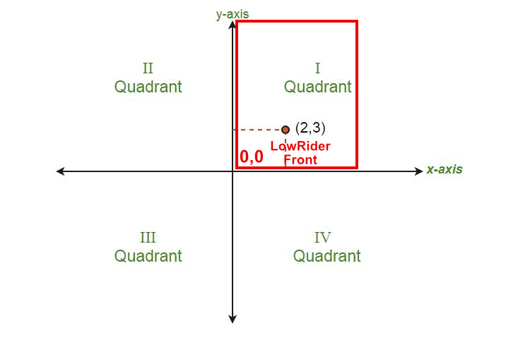
Nothing is mirrored in that configuration. It’s just rotated 90º right?
So CAM should be normal, I would think, except that his boards have to be rotated also.
Standing at the side, (0, 0) is still his bottom left, so the coordinate space is fine for CAM.
Just that it’s a little more trouble dealing with looking around the X Gantry and router, etc., right?
I think it’s more of a pain than it’s worth to do it that way, but I don’t think it presents any challenges except that the he has to remember to rotate the stock… and support is trickier.
Below is an edited version of your config.yaml file shown in the first post, that seeks to implement the approach I suggested in the quote above.
Also, I noticed that your values for pulloff_mm, at 10, are larger than normal, which may be no issue for you, but since somewhere between 4 to 5 is normal, at 10, you are giving up some cuttable area that you could keep. If you do decide to try this, let me know if it does right for you!