How to Edit [MSG:INFO: Axis X (-817.000,3.000)]

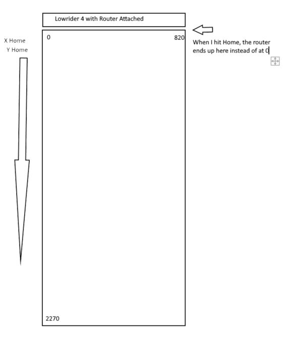
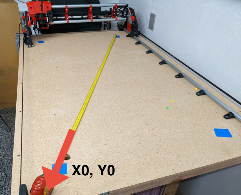
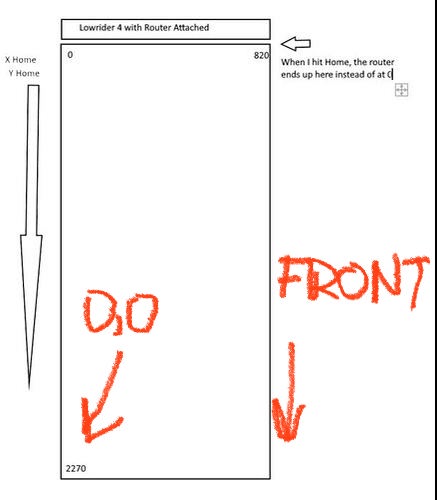
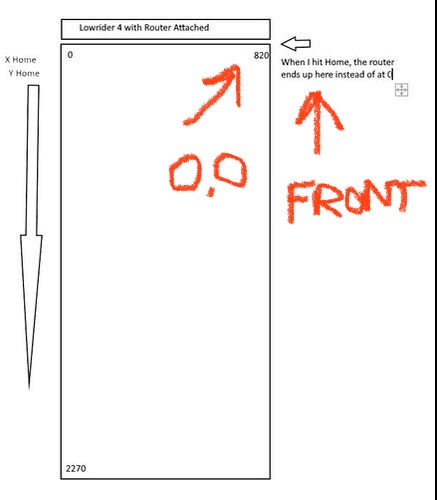
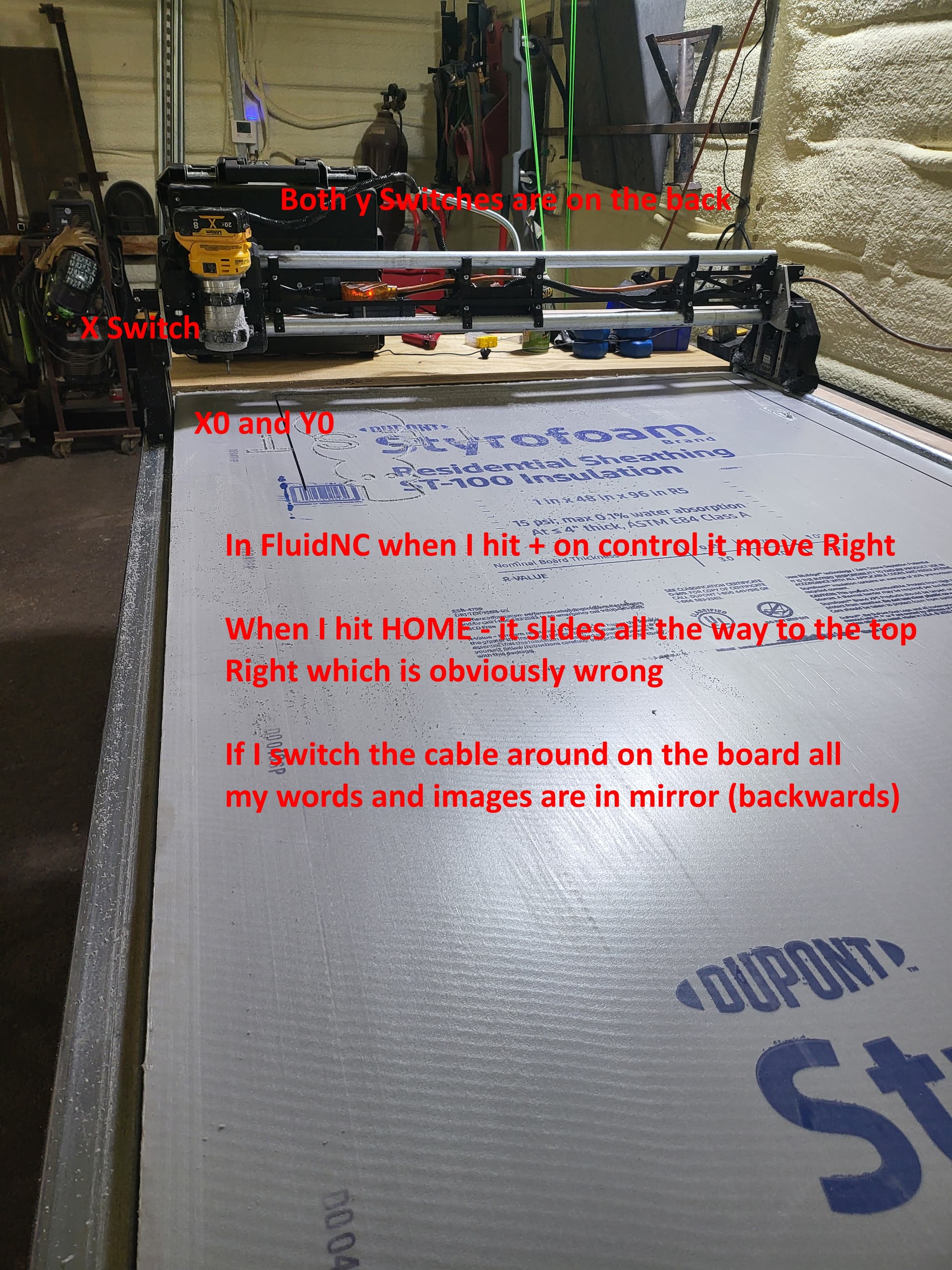
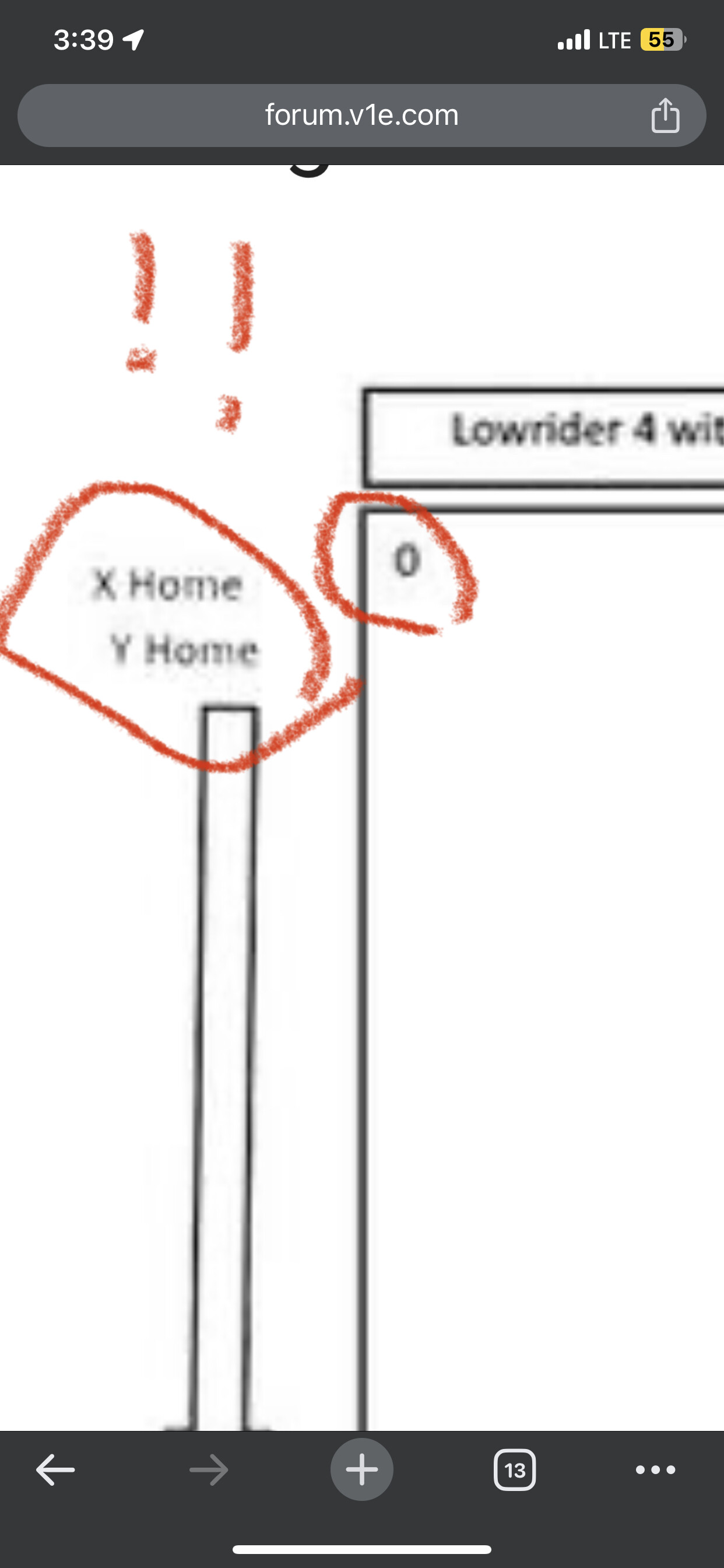
I am at wits end. I have everything working correctly except I can’t get X home to be bottom right if I am standing behind the machine to Top Left if standing in front of machine. With a 6’ x 20 foot table I can’t reach X on the other side. Below is my yaml file and I have read 42000 pages but no one syas what the command is to change this, just to change it… When I hit X home it goes Top right not Top Left :frowning:

board: Jackpot TMC2209
name: LowRider
meta: 12-22-2024 NetworkLarry
stepping: 
  engine: I2S_STATIC
  idle_ms: 255
  pulse_us: 2
  dir_delay_us: 1
  disable_delay_us: 0
  segments: 12

uart1: 
  txd_pin: gpio.0
  rxd_pin: gpio.4
  rts_pin: NO_PIN
  cts_pin: NO_PIN
  baud: 115200
  mode: 8N1

i2so: 
  bck_pin: gpio.22
  data_pin: gpio.21
  ws_pin: gpio.17

spi: 
  miso_pin: gpio.19
  mosi_pin: gpio.23
  sck_pin: gpio.18

sdcard: 
  cs_pin: gpio.5
  card_detect_pin: NO_PIN
  frequency_hz: 20000000

kinematics: 
  Cartesian: 

axes: 
  shared_stepper_disable_pin: NO_PIN
  shared_stepper_reset_pin: NO_PIN
  homing_runs: 2
  x: 
    steps_per_mm: 50.000000
    max_rate_mm_per_min: 9000.000000
    acceleration_mm_per_sec2: 200.000000
    max_travel_mm: 820.000000
    soft_limits: false
    homing: 
      cycle: 2
      allow_single_axis: true
      positive_direction: true
      mpos_mm: 3.000000
      feed_mm_per_min: 300.000000
      seek_mm_per_min: 1500.000000
      settle_ms: 500
      seek_scaler: 1.100000
      feed_scaler: 1.100000

    motor0: 
      limit_neg_pin: gpio.25
      limit_pos_pin: NO_PIN
      limit_all_pin: NO_PIN
      hard_limits: false
      pulloff_mm: 10.000000
      tmc_2209: 
        addr: 0
        cs_pin: NO_PIN
        uart_num: 1
        step_pin: I2SO.2
        direction_pin: I2SO.1
        disable_pin: I2SO.0
        r_sense_ohms: 0.110000
        run_amps: 0.800000
        hold_amps: 0.700000
        microsteps: 8
        toff_disable: 0
        toff_stealthchop: 5
        use_enable: false
        run_mode: StealthChop
        homing_mode: StealthChop
        homing_amps: 0.800000
        stallguard: 0
        stallguard_debug: false
        toff_coolstep: 3

  y: 
    steps_per_mm: 50.000000
    max_rate_mm_per_min: 9000.000000
    acceleration_mm_per_sec2: 200.000000
    max_travel_mm: 2740.000000
    soft_limits: false
    homing: 
      cycle: 2
      allow_single_axis: true
      positive_direction: false
      mpos_mm: 3.000000
      feed_mm_per_min: 300.000000
      seek_mm_per_min: 1500.000000
      settle_ms: 500
      seek_scaler: 1.100000
      feed_scaler: 1.100000

    motor0: 
      limit_neg_pin: gpio.33
      limit_pos_pin: NO_PIN
      limit_all_pin: NO_PIN
      hard_limits: false
      pulloff_mm: 10.000000
      tmc_2209: 
        addr: 1
        cs_pin: NO_PIN
        uart_num: 1
        step_pin: I2SO.5
        direction_pin: I2SO.4
        disable_pin: I2SO.7
        r_sense_ohms: 0.110000
        run_amps: 0.800000
        hold_amps: 0.700000
        microsteps: 8
        toff_disable: 0
        toff_stealthchop: 5
        use_enable: false
        run_mode: StealthChop
        homing_mode: StealthChop
        homing_amps: 0.800000
        stallguard: 0
        stallguard_debug: false
        toff_coolstep: 3

    motor1: 
      limit_neg_pin: gpio.35
      limit_pos_pin: NO_PIN
      limit_all_pin: NO_PIN
      hard_limits: false
      pulloff_mm: 10.000000
      tmc_2209: 
        addr: 3
        cs_pin: I2SO.14
        uart_num: 1
        step_pin: I2SO.13
        direction_pin: I2SO.12
        disable_pin: I2SO.15
        r_sense_ohms: 0.110000
        run_amps: 0.800000
        hold_amps: 0.700000
        microsteps: 8
        toff_disable: 0
        toff_stealthchop: 5
        use_enable: false
        run_mode: StealthChop
        homing_mode: StealthChop
        homing_amps: 0.800000
        stallguard: 0
        stallguard_debug: false
        toff_coolstep: 3

  z: 
    steps_per_mm: 200.000000
    max_rate_mm_per_min: 1800.000000
    acceleration_mm_per_sec2: 80.000000
    max_travel_mm: 300.000000
    soft_limits: false
    homing: 
      cycle: 1
      allow_single_axis: true
      positive_direction: true
      mpos_mm: 3.000000
      feed_mm_per_min: 200.000000
      seek_mm_per_min: 800.000000
      settle_ms: 500
      seek_scaler: 1.100000
      feed_scaler: 1.100000

    motor0: 
      limit_neg_pin: NO_PIN
      limit_pos_pin: gpio.32
      limit_all_pin: NO_PIN
      hard_limits: false
      pulloff_mm: 10.000000
      tmc_2209: 
        addr: 2
        cs_pin: NO_PIN
        uart_num: 1
        step_pin: I2SO.10
        direction_pin: I2SO.9
        disable_pin: I2SO.8
        r_sense_ohms: 0.110000
        run_amps: 0.800000
        hold_amps: 0.700000
        microsteps: 8
        toff_disable: 0
        toff_stealthchop: 5
        use_enable: false
        run_mode: StealthChop
        homing_mode: StealthChop
        homing_amps: 0.800000
        stallguard: 0
        stallguard_debug: false
        toff_coolstep: 3

    motor1: 
      limit_neg_pin: NO_PIN
      limit_pos_pin: gpio.34
      limit_all_pin: NO_PIN
      hard_limits: false
      pulloff_mm: 10.000000
      tmc_2209: 
        addr: 3
        cs_pin: I2SO.19
        uart_num: 1
        step_pin: I2SO.18
        direction_pin: I2SO.17
        disable_pin: I2SO.16
        r_sense_ohms: 0.110000
        run_amps: 0.800000
        hold_amps: 0.700000
        microsteps: 8
        toff_disable: 0
        toff_stealthchop: 5
        use_enable: false
        run_mode: StealthChop
        homing_mode: StealthChop
        homing_amps: 0.800000
        stallguard: 0
        stallguard_debug: false
        toff_coolstep: 3

control: 
  safety_door_pin: NO_PIN
  reset_pin: NO_PIN
  feed_hold_pin: NO_PIN
  cycle_start_pin: NO_PIN
  macro0_pin: NO_PIN
  macro1_pin: NO_PIN
  macro2_pin: NO_PIN
  macro3_pin: NO_PIN
  fault_pin: NO_PIN
  estop_pin: NO_PIN

coolant: 
  flood_pin: gpio.2
  mist_pin: gpio.16
  delay_ms: 0

probe: 
  pin: 'gpio.36:low'
  toolsetter_pin: NO_PIN
  check_mode_start: true
  hard_stop: false

macros: 
  startup_line0: 
  startup_line1: 
  Macro0: 
  Macro1: 
  Macro2: 
  Macro3: 
  after_homing: 
  after_reset: 
  after_unlock: 

start: 
  must_home: false
  deactivate_parking: false
  check_limits: true

parking: 
  enable: false
  axis: Z
  target_mpos_mm: -5.000000
  rate_mm_per_min: 800.000000
  pullout_distance_mm: 10.000000
  pullout_rate_mm_per_min: 250.000000

user_outputs: 
  analog0_pin: NO_PIN
  analog1_pin: NO_PIN
  analog2_pin: NO_PIN
  analog3_pin: NO_PIN
  analog0_hz: 5000
  analog1_hz: 5000
  analog2_hz: 5000
  analog3_hz: 5000
  digital0_pin: gpio.26
  digital1_pin: gpio.27
  digital2_pin: NO_PIN
  digital3_pin: NO_PIN
  digital4_pin: NO_PIN
  digital5_pin: NO_PIN
  digital6_pin: NO_PIN
  digital7_pin: NO_PIN

user_inputs: 
  analog0_pin: NO_PIN
  analog1_pin: NO_PIN
  analog2_pin: NO_PIN
  analog3_pin: NO_PIN
  digital0_pin: NO_PIN
  digital1_pin: NO_PIN
  digital2_pin: NO_PIN
  digital3_pin: NO_PIN
  digital4_pin: NO_PIN
  digital5_pin: NO_PIN
  digital6_pin: NO_PIN
  digital7_pin: NO_PIN

arc_tolerance_mm: 0.002000
junction_deviation_mm: 0.010000
verbose_errors: true
report_inches: true
enable_parking_override_control: false
use_line_numbers: false
planner_blocks: 32

Not really sure from your description what is happening and what you want to happen.

To remove ambiguity can you post a picture of your lowrider with where it’s currently homing to and where you want it to home to?


Here is a picture

X home means move left until it hits the endstop. If that is not happening, you do not have it wired correctly.

Y home means move to the bottom (in your picture).

In that diagram is the router on the top or bottom of the X gantry as you’ve drawn it?

When X homes does it home to the non-rail side?

To clarify this is the default. I know that’s a LR3 but the LR4 is the same, note the router facing towards you.

1 Like

Your picture is correct except my x0 and y0 is top left not bottom left and when it homes it homes to the Rail side but I wanrt it to home to the non-rail side

https://docs.v1e.com/software/reverse-motor/

X+ should move your router to the right, if it does not do that you need to flip the plug with the board completely powered off.

Y+ should move the router away from you, if that is not the case both Y plugs need to be flipped.

Looking at it from the perspecive of Dretfus’s picutre it does indeed move Right aka away from o but when I hit home it goes to 820 -3 IE 817.

So you want x to home as per stock and Y to home to the far end.

Since you didn’t post a picture can you confirm you ONLY have end stops on the stepper motor side of the core (the stock, default) and the BACK of the YZ plates (away from the core side)

Just for clarity, this photo shows the stock orientation of a standard LowRider, homing to your left in the x-axis and near you in the y-axis. Is this what you are after? Or are you wanting something non-standard?

Yes, that is what I want. I have end stops of the left or the X and the 2 y’s are on the rear and of course Z’s are when it gets to the top.

If you include the + and - for positive and negative movement directions that’s diagrams a keeper.

1 Like

Back to the core answer - how do I reset the MACHINE X to be 0,0 instead of -817,3 ?

Standard would be with the Y limit switches on the fronts of the two side assemblies — facing toward you, and the Y is homing toward you. To change the Y so as to be homing away from you, with limit switches on the backs of the side assemblies, would constitute (mathematically speaking from a CAM perspective), a non-standard and non-workable arrangement unless you swap X and Y axes (which I have done and it works).

A standard LowRider can either home to the “near left” or — by flipping the plug wiring orientations on the X stepper and both of the Y steppers, to the “far right.” To home in either of the other two corners, “near right” or “far left” would be a case when you need to swap your X and Y axes or else your CAM file output is not going to work right.

It’s easy to be misunderstood and to misunderstand — so I’m doing my best to follow, but if you’re saying that homing X is moving in the wrong direction, and you wanted to move in the correct direction, then it simply means that the stepper wire for the X axis is plugged in backwards. As Ryan already mentioned, you can power down your board completely, pull that stepper’s wiring plug loose from your control board, flip it around, and plug it back in. That will make the X homing action go to the other side.

If you want it homing in the same direction it’s currently homing, but you want to “change” the numeric designation of a non-standard homing location to be a new zero, then it sounds like you are in a case of “the corner you want to home to would call for swapping your X and Y axes”.

You always need to be able to have a homing location where X and Y form of nexus of 0,0

I may still not be understanding what you are after, and don’t be frustrated by that as there’s lots of ways to describe things, and it can be easy to be misunderstood.

The “minimum” and “maximum” wording was intended to explain, but I do need to explicitly put the minus and plus signs on there.

To try to add a bit more clarity, as your drawing did not indicate which side of the gantry is reckoned as the front, I have made two modified versions of your drawing, showing the two corners that a standard LowRider came home to, without swapping the axes — and you can switch from one of these to the other by flipping the stepper wire plugs of the X and both of the Y steppers where they meet the control board, while the control board is turned off. Obviously, the Y axis limit switches need to be on the appropriate end of the side assemblies, front side for homing to the front or to the rear for homing to the rear, and the X axis limit switch would need to be on the left side of the core for homing to the left, or on the right side of the core for homing to the right.

image

image

If you are homing to the far right while the front of the machine is actually near, indicating a near left homing should be happening, then, all of your stepper wires need flipped at the board while it is powered down.


Time for a Picture with words

1 Like

Your photo helps to bring clarity.

With a standard LowRider, 0,0 for homing is near you and on the left side. Hitting the + in Y moves away from you toward the back, and hitting the + on the X moves toward the right. Your drawing designates 0,0 in the wrong corner. The only way to have 0,0 function in that corner is if you swap your X and Y axis (logically speaking) within your config file.