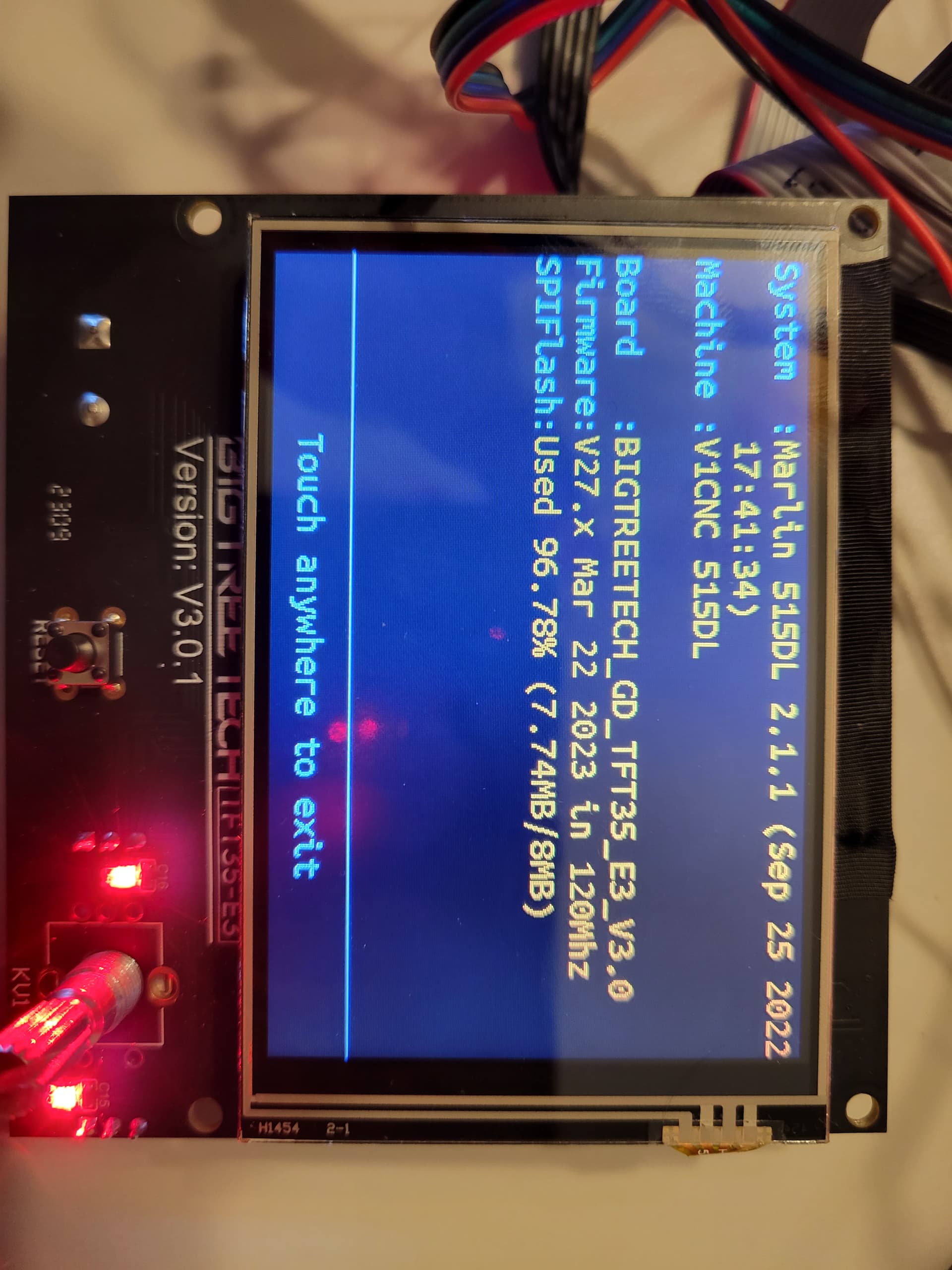
The 515DL marks that firmware as version 515 dual end stop Low Rider. The same firmware for the LR2 and LR3 works, so you definitely have the correct firmware for a LowRider3.
The stop switches should be wired in normally closed mode. These are (usually) the 2 outside edge pins on the switch. The center pin is not used. It does not actually matter which one is ground and which is signal. On the main board, they should be connected to the signal and ground pins. The +5V pins are not used.
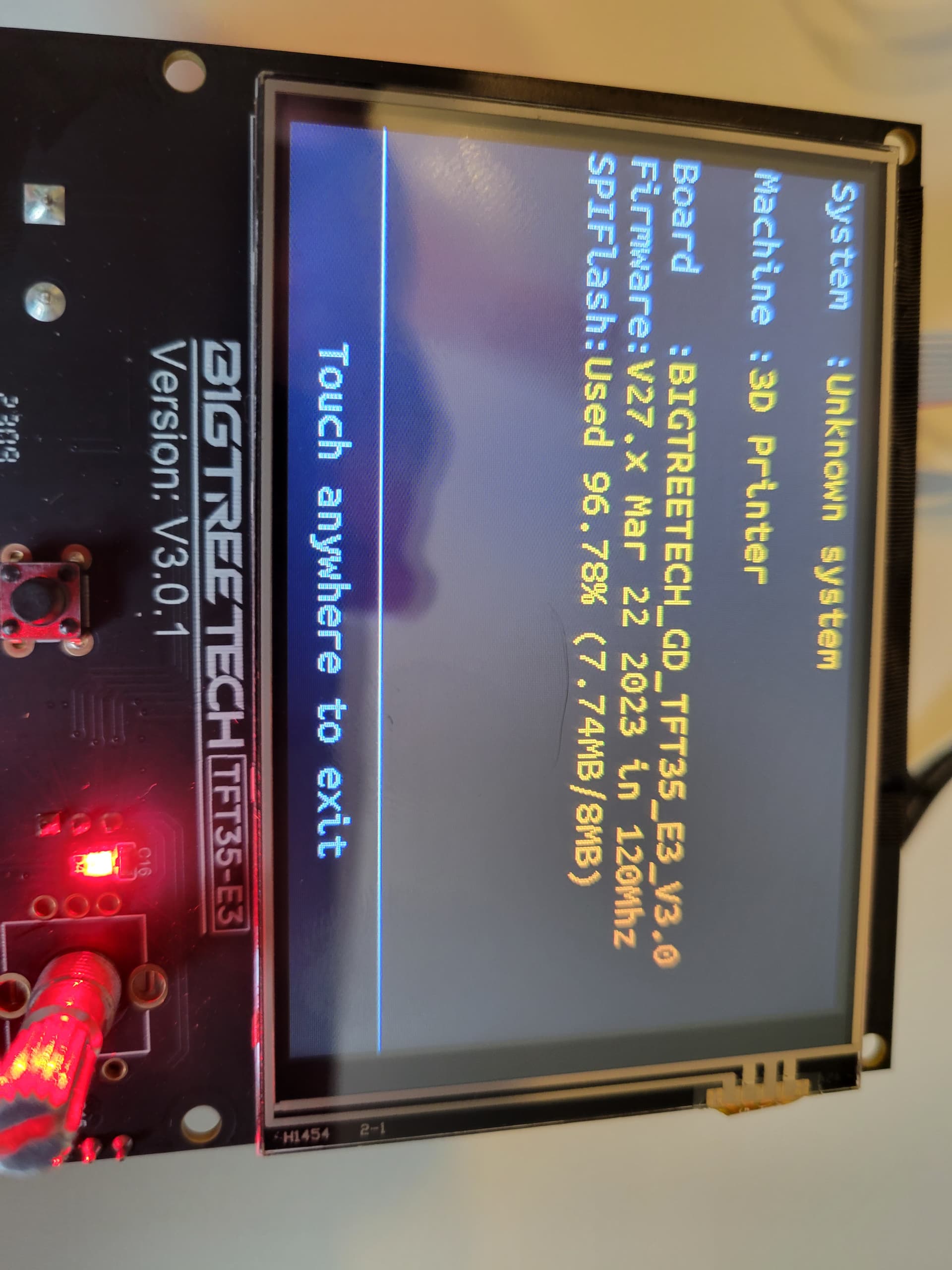
The TFT is still very much aimed at 3D printing, and so it will look like it is configured for 3D printing, with functions that are aimed at it as well (like filament unload) we can safely ignore that. There have been CNC specific builds for the TFT, but they do not work on the GD processor version of the TFT which you have. The firmware that you have for the TFT seems correct.
You may have your end stop switches incorrectly or incompletely connected.
This is from memory, please check docs.
There are 7 motor connections on the SKR Pro 1.2. From the power connectors they are X, Y, Z, Z, E0, E1, E2. They should be connected as follows:
- X → X motor
- Y → Y1 motor
- Z → Z1 motor
- Z2 → left with jumpers over the pins
- E0 → Y2 motor
- E1 → Z2 motor.
End stops are labelled as X, Y, Z, E0, E1, E2.
- X → X end stop switch on the core
- Y → Y1 end stop. This must be the same side as the Y1 motor on the Y motor connector
- Z → touch plate probe
- E0 → Z2 end stop. This is the same side as the Z2 motor on the E1 motor connector
- E1 → Y2 end stop. This muist be the same as the Y2 motor connected to the E0 motor connector
- E2 → Z1 end stop. This is the same side as the Z1 motor connected to the Z motor connector
Some of this sounds a bit weird, but it’s because Marlin treats the X Y and Z all as minimum side stops, so the Z stop cannot be used for a maximum limit switch. Though the other switches are labelled as E0, E1, E2, they are treated as X Max, Y Max, and Z Max.
If you do not have a switch connected (Or if you have the touch plate connected to the Z stop connector) then the stop will read as “triggered” and the motor will not move during homing. It may move about 5mm or so in the wrong direction after the other switch is triggered.
Edit: Use the command “M119” to check the status of your end stops.