First, the Sketchup sizing issue has been resolved. Parallel Projection. That’s all.QCAD verifies that the long sidfe is exactly 2500mm. Whew.
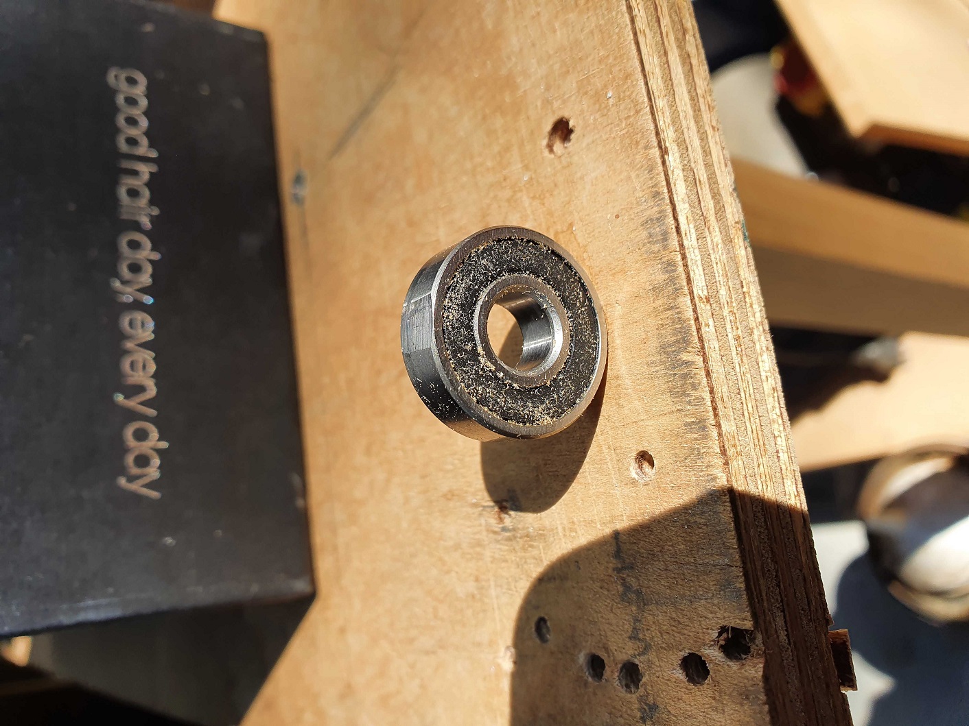
My Z-axis (on the near side where the electrics are) “jumps” from time to time. It seems to stick, and then release. This has been driving me nuts. So I checked that the tensions on all the wheels were right (fingers can rotate the bearings, no visible gaps) And then I noticed it. One of the bearings had a flat surface - almost like a flat tyre. I doubt that this was the cause of the jerking - since the bearing should have slid over the SS pipe anyway. But I slacked off the pressure a bit just to make sure, and because Ryan’s kit includes a few spare bearings, it replaced it, and carefully made sure contact was being made between the bearing and the pipe, but I could still move the bearing with my fingers. So far, so good - no sticking/jerking on up/down movements
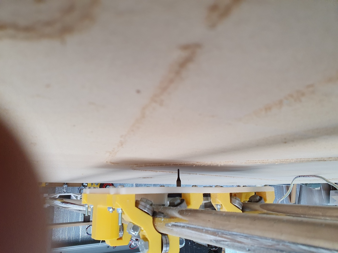
It turns out my bed is quite badly concaved - buy almost 3mm. So while the cuts are nice and clean at the edges of the X-axis, by the time the router bit is in the centre, it isn’t even touching the bed. (See pic). How do I resolve this? From what I gather, i have three options: (1) Level the bed using a planing bit (basically cut a pocket) (2) Build up a 3mm border all round the bed, and pour in some extremely low viscosity resin - the kind they use for vacuum infusion - the stuff is like water) That will absolutely ensure a perfectly flat surface (3) Do both.
My wheels run in two channels with a 8mm deep groove routered out along their lengths. The wheels do not touch the bottom of the groove. There is a 2mm - 3mm clearance. I would need to use the resin to level these grooves alsoThat way the rails and the bed are both as level as possible.
I wouldn’t mess with leveling with epoxy. It’s a waste board after all. What kind of support does the center of your table have? Maybe it needs to be built or jacked up a bit. Other than that id flatten it with the router.
Hi,
Yep = a pretty weird bearing. The support for the bed is a humungusly heavy table I sourced somewhere. On top of that I’ve laid a panel of chipboard used for flooring here in Aus. And then I have 20mm plywood. Weird thing is, the chipboard seems to be pretty flat, but the plywood isn’t. I’m now going to remove the plywood, and use the chipboard as the sacrificial layer.
My electric drill has decided that it’s a waste of time staying charged for more than an hour or so. Same (coincidentally) for the electric screwdriver. Need to pop into Bunnings and get new batteries, I think.
The router is on order. Delivery mon-Fri next week. But maybe the chipboards by themselves will do the trick till then.
At first I thought this was upside down, but then I realized this is probably normal for Australia since gravity pulls upward.
I think it’s important to have a mental model or theory within which the measured error is plausible, and then calibration is a good thing to get accuracy.
If the error is implausible or if there is low understanding and the error is not known to be plausible or implausible, then there is a high chance of applying the wrong fix. Maybe there was a 3mm goof in the tool diameter in CAM, and fixing with steps per mm might create a proper size test square but compound the problem so it’s worse, not better.
For plenty of people it is hard to know how much error is plausible or implausible, and from the outside it’s hard to know how well a person will judge what is plausible. And for me at least, this tilts the recommendation toward “let’s understand every element” and away from “let’s add a scale factor”.
But in cases where there is confidence in the person or the experiment, then I have no reservations when it comes to fudge factors.
Hi. New challenge:
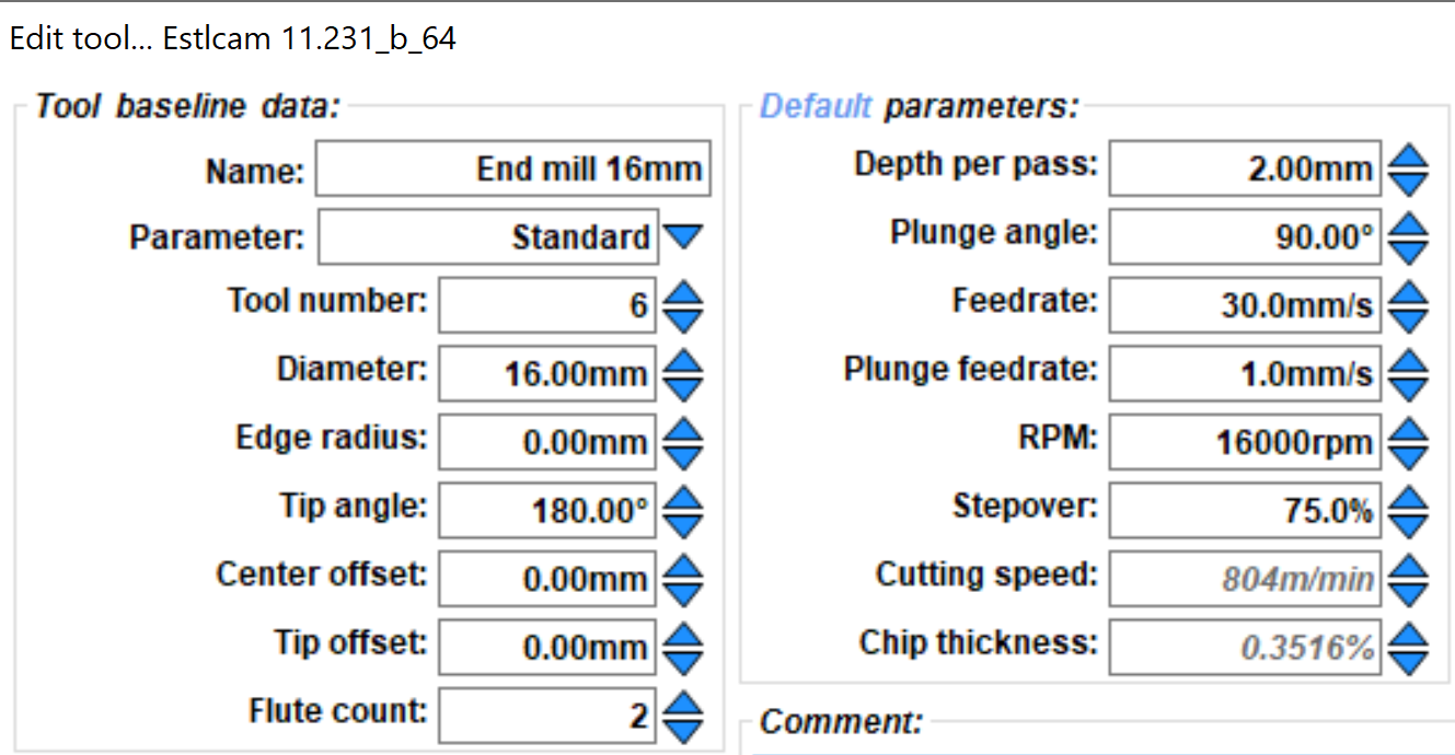
I used a 16mm straight bit to re-surface my waste-board. Wow! It had some extremely high spots, and some slots that were too low for even 3mm of bed levelling to touch. But the waste board is 21mm thick, so I have a good safety margin.
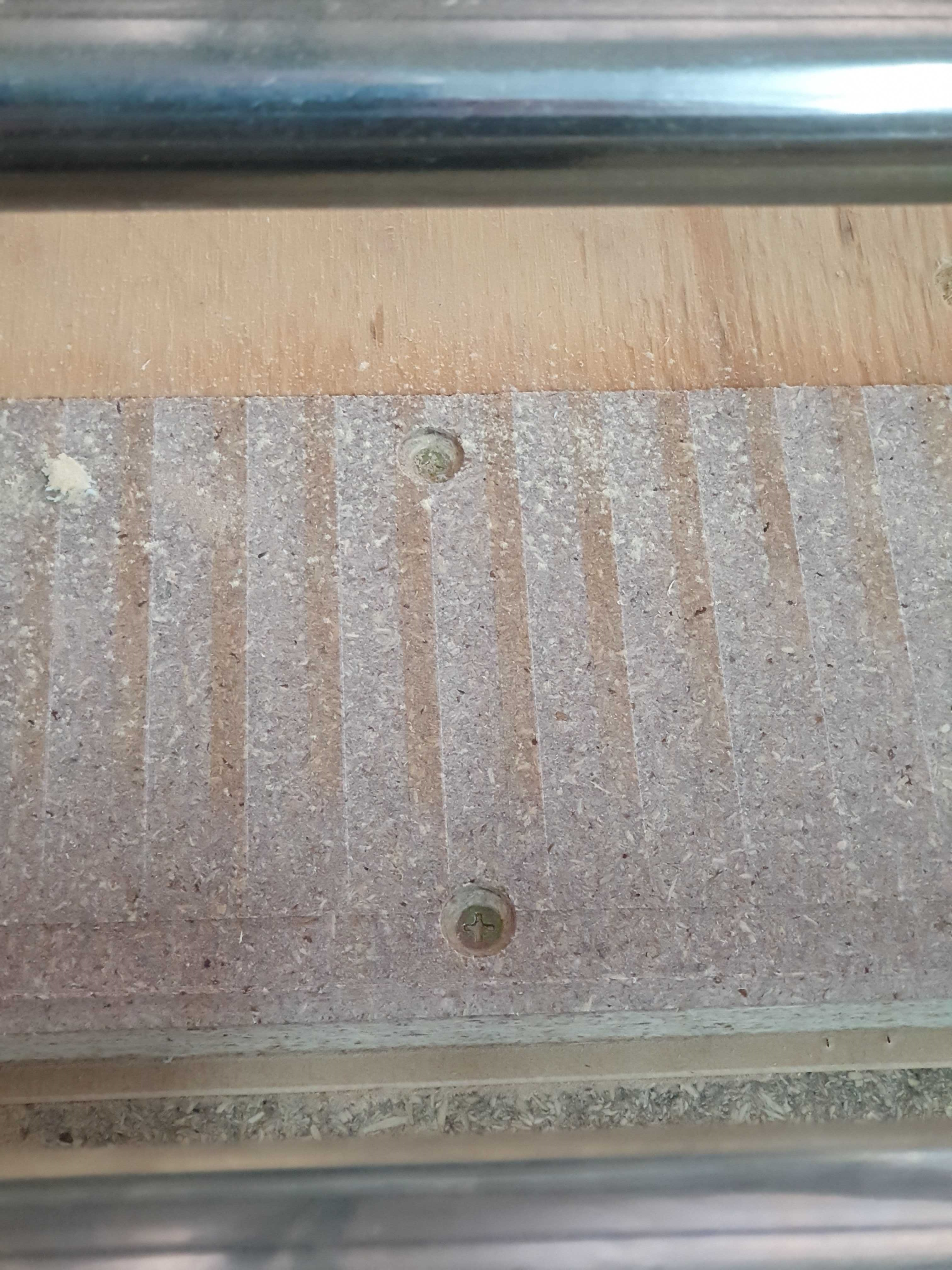
Problem is, I’m using Estlcam to create a pocket for the entire 2440 x 1220 bed, with 75% stepover. So far, so good. Except that each 2nd pass of the bit leaves a ridge (see photo)
The tool:
Can anyone see what I’m doing wrong? I’ve checked the verticality of the router but by mounting a 6mm rod and checking all sides for 90 deg. As far as I can tell, it’s all good. Is my feed rate too high? Stepover OK? RPM?
I have a 30mm planing bit arriving next week, but I thought I’d get a head start with the 16mm bit.
The two things that come to mind are if the bit is not perpendicular or if it is deflecting under load.
If the bit is not perpendicular then one side cuts deeper than the other. If the direction of travel has the deeper side leading, then it will cut at the outer edge, but if the deeper side is trailing, it will cut using the bottom, which I’ve seen leave scorch marks.
You checked that it’s perpendicular but when it’s under load it could deflect away from perpendicular. In one direction the tool deflects one way and in the opposite direction the tool deflects the opposite way. This can also affect depth since the pivot is not exactly above the tool, which can lead to ridges even if your tool is perpendicular to start with.
I didn’t find an easy way to force CAM to cut in only one direction, and it is simple enough that I wrote a surfacing generator for my test pattern generator. You can specify the direction for cutting, so if you know which way your router is tilted you can cut with the deeper side leading. It also uses many short movements so you can use Octoprint’s feedrate adjustment while the job is running with only a little bit of lag.
Not sure from your description how you checked level, but a simple tramming setup with a long arm will give you accurate readings. Here is one from Thingiverse: https://www.thingiverse.com/thing:4128469 And if you search on this Forum for ‘tramming’, you will find pictures of a couple more.
To check for deflection, try a few very slow passes with shallow depth of cut and compare that to what you are getting. Your setting of 2mm for DOC seemed aggressive for a larger bit.
Don’t know if it is available in Estlcam, but in Fusion 360, the direction of the cut is controlled by setting ‘Direction’ to ‘climb’, ‘conventional’, or ‘both’. So you can look to see if those terms are available in your Estlcam facing operation.