Build: Purchased SKR Pro 1.2 and TFT through V1 Engineering; updated TFT firmware with latest build
I am able to home the Y and Z axes reliably. However, the X axis fails to home every time. Manually pressing the switch causes the X axis LED to turn on, so that’s working. Strangely when I executed the squareness marks gcode, the X axis drove to the correct limit I set in the script generator, pauses, then drives the X-axis into the Z-plate, grinding until I hit reset.
I moved the carriage manually to just before the X-axis endstop would engage. Then, I hit HOME → X using the touch screen controls. Invariably, the carriage moves away from the endstop. It even does the short back and forth as though it found the end stop. Repeating the HOME → X will move it even farther away from the physical endstop switch. Some exact behavior with the Repetier host.
Note that the X-axis moves in the correct direction using the touch screen or Repetier host. It also functioned enough to print the crown pattern.
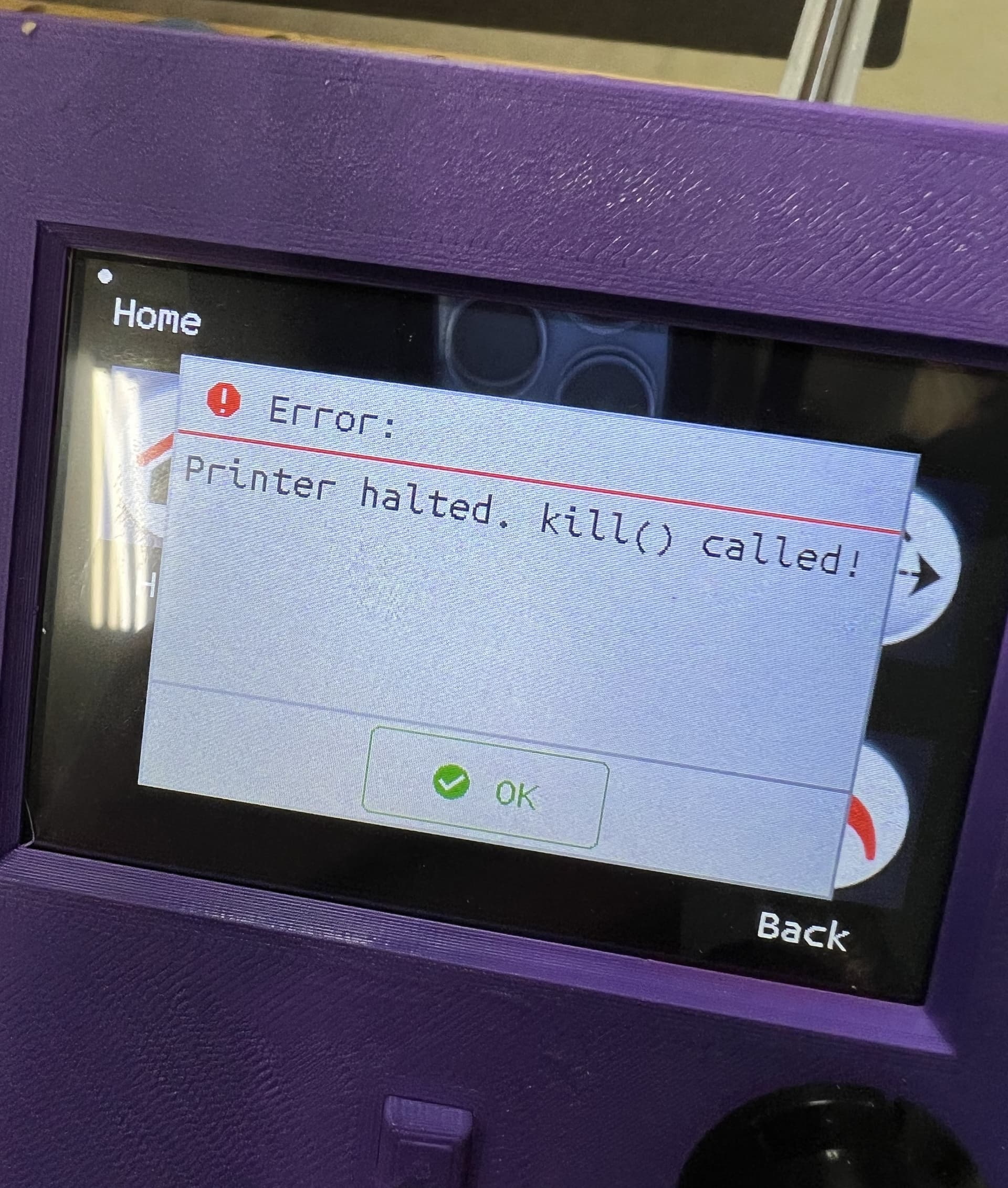
If I try to drive the X-axis with the touch screen controls or the Repetier host, after a few 1mm movements, I get the error: Printer Halted. kill () called! (see picture).
I’ve checked the endstop wiring with a voltmeter and there’s continuity. The LED associated with the endstop can be turned on and off by pressing the microswitch (turns on when switch is depressed).
I’m really at a loss here trying to figure out what’s wrong. Could it be a problem with the stepper motor or the SKR Pro board?
I don’t have a precise answer for you. Hope following info helps…
This is good. Does output from M119 command match whether you have end stop switches pressed? Knowing if you’re seeing a mismatch between M119 and LED lights when switches are pressed will help narrow down possible cause(s).
Ran into something similar when I didn’t have the right movement mode set. Already know about G90 Absolute and G91 Relative movements?
You probably know already, but don’t move parts manually too quickly, could generate voltage/current that could potentially damage the controller/drivers. Someone please chime in and correct me if I’m wrong.
I know this is a basic question but where would I see the output of M119? And when is the M119 command issued? Or do I type that into repetier or the onboard TFT interface? Really sorry, totally new to this.
The code I used for the squareness marks is autogenerated using the link in the instructions. I checked and it uses G92 X0 Y0 Z0. Not sure if that’s relevant. I don’t see any G90 or G91 commands in the gcode. But thanks so much for the link to the Marlin fw. Lots in there to digest!
I’ve been careful when moving the carriage. With no power to the board, I unplug the stepper motor and move the carriage. I did once move it with the stepper plugged in and saw a light turn on the board. Maybe I need to buy a new board?
I know this is a basic question but where would I see the output of M119?
In Repetier-Host, under the Manual Tab, you can type the M119 in the G-Code field and click “Send.” I don’t have a TFT to verify, but I believe there is a console mode where you can type in g-code commands and get back a result.
So…the end stop wiring was faulty. It was a loose connection that would trigger the end stop when the gantry moved. Ugh. So that’s fixed. Thank you for all the hellp.
I’m still unable to run the squareness marks test code. At the second mark, it drives the gantry into the z plate. It seems to be using relative coordinates rather than absolute even though the autogenerated code uses g92 at the beginning and everything else is G1 or G0. Is it possible that homing somehow locks it into absolute mode? Has anyone else had trouble using the script to generate the squareness gcode?
Posting this code to the forum might help sort out whatever is going on. If your script is using relative coordinates, it needs to have a G91 at the top of the file to put Marlin in relative mode.
Thanks. If I’m interpreting the code correctly, it should not be in relative mode. I entered smaller extents for this test.
It seems to be driving X to 590 correctly but then I think it’s trying to drive an additional 600mm relative to the 590 position instead of driving to absolute 600, or only 10mm. Code is below.
Edit the above g-code file, and put a G90 just above the G92 in the file. Run it again, and see what happens. The G92 will not have any impact relative to absolute vs. relative movements. How are you delivering this file to your control board? If you are using a g-code sender, take a look at the start code to see if there are any additional g-code commands being sent, since they will not appear in this listing. If, after inserting G90, you still have issues with X and Y movement, look for a mechanical issue…loose grub screws, or something binding, or pen not being raised and dragging, etc.
I ran your code through a g-code simulator, and it worked fine. The only thing that stands out is the feedrate for Z. A feedrate of 800 mm/min is nearly twice what Ryan recommends as the maximum feedrate in his EstlCAM setup page. I have a Primo, not a Lowrider, so 800 may be reasonable for a Lowrider. A feedrate too high for the steppers will result in lost steps, particularly when raising the steppers. The result might be the Z being driven into the spoil board.