I am working on a home made laser using an SKR Pro 1.2 board with a TFT35 E3 screen. I am using the Lowrider firmware because it is similar to my build except I do not have 2 z axis so I commented that out in the code.
The problem I am having is I would like my machine to home to X Min, Y Max, Z Max. When I change the line for homing to Y Max and try to build the firmware in platform IO I get a fail in the endstops.h file for “Y_MAX was not declared for this scope; did you mean Z_MAX?” if I change Y home back to -1 in configuration.h, it builds with no problems. Also if I load this bin to the board everything homes in the expected direction.
My reasoning for this is so that my machine will home with the gantry in the back left corner making the cutting bed easier to load material into.
My limit switches are wired so that the Min and Max switch are in series and plugged into the same port on the board. Y is plugged into the Ymin port and Y2 is plugged into the Ymax port as laid out in the duel end stop tutorial.
The easiest solution is to just make a macro that homes and then jogs to the Ymax position.
Marlin does some funny logic when you change the HOME_DIR on a dual axis. When the dir is -1, Y1 is Ymin and Y2 is Ymax (by default). When you change the dir to +1, Ymax is Y1 and Y2 is also Ymax (defined in the configuration_adv.h). But you can’t set Y2 to Ymin, because the safety check code still think Ymin is used. I think the solution is to change Y2 (in configuration_adv) to Xmax. It shouldn’t interfere on your build because you don’t have a Z2.
Another hack beyond what is suggested by Jeff is to probe for the max Y position. You would need to connect your Y Max switch in parallel whatever pin you are using for probing.
Personally, I have three different switches connected to my probe pin. I have a bit setter switch, a touch probe and a max Z switch. Which is targeted depends on the script that I execute.
Using probing is a hack, but it would get the job done.
Min and Max switch are in series
I think you mean parallel instead of series. You would have problems if you wired these switches in series.
Normally closed switches in parallel require that all switches be triggered in order to read an event. Typical V1 switches are wired normally closed.
The normally closed switch is a short circuit, and the pin doesn’t actually care if there is 1 or 2 (or three) short circuits it will “read” it as 0 ohms.
From a logic standpoint it’s an and gate. Only is A and B are triggered is the circuit triggered.
Normally open switches in parallel, will read as triggered if any one is triggered. In logic terms, it’s an or gate. It will read triggered if either A or B (or both) are triggered.
So your multiple switches on one pin in parallel works in this case. It requires that the firmware be modified to expect a NO switch instead of the default NC switch though
Switching to series reverses the and/or gate logic. NC switches in series becomes an or gate, NO switches in series becomes an and gate. Either series or parallel can work depending on how you set it up.
Bonus logic: an xor gate can be set up using 3 pin switches. Connect the C pin of one switch to the stop pin and the other to ground. Link NC to NC and NO to NO between the switches. If neither switch is touched, or if both switches are triggered, you get 0 ohms. You get infinite ohms if either A or B are triggered. (This is the same as a 3-way light switch in your house.) Not really useful for CNC pins, though.
Thank you for the replies, doing a macro was the direction I was starting to head. I’m used to linux cnc where it is a bit easier to set up the limit switch logic. By macro do you mean in the custom gcode file? So write “g28 g01 F??? Y ??” And give it a name like home?
Never thought of the switches as logic gates thought, that was a fun bit of info thank you. Dan
Ok next issue i have been running into that has me stumped. I’m using lightburn as my CAM solution to make my gcode files. When i save them light burn adds a M2 (end program) to the code which has caused the echo to report an unknown command and sometimes sends my Z axis full speed towards the bed causing a hard crash (no limit switch, probably going to fix that soon) unless i kill the power to stop it.
Any ideas how to fix that besides just removing the m2 command manually from the file? Looks like marlin does not use it. Still looking into this probably headed to the lightburn forum with other questions related to then specificity.
I use Lightburn, and I don’t get an M2 at the end of my program. Are you sure you set up Lightburn for Marlin output when you created the device? If so, are you sure you are using that device?
Z axis full speed towards the bed causing a hard crash
Are you sure the M2 is causing the problem? Is it possible your steppers are being disabled (by command or my time), and your router is falling towards the bed? Look for an M18 or an M84. Marlin seems to ignore all unknown commands, so you might look beyond the M2 for an alternate cause for the crashes.
Dan: Good catch on the parallel vs. series. I didn’t think things through and was visualizing my Z axis, which has normally open switches.
For some reason the only option to fire the laser with the marlin profile is with M106 sometimes i use a different cam solution that uses M4 so I’m using a profile that uses m4 to fire the laser with Lightburn. Also I’m just using lightburn for gcode not for running the machine.
As for the z gravity falling its a stepper on a lead screw and it will hold its position even with power off. I have had the run away z 2 times now both of them were after hitting ok on an error message. The g code file did not have any z commands in it.
A quick look on the lightburn forum I may have found the fix for the m106 vs m3/m5 issue I am having I’ll look when I get home. That should remove the m2 from my code.
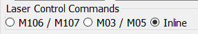
Assuming you have your laser connected to the laser pin defined in the firmware, you will get superior results by using inline commands. In Lightburn Device/Basic Settings, set the output:
You will also need the following at the top of the file to enable inline commands in Marlin:
M3 I
This can be added Device Settings/GCode/Start GCode so that it is automatically added to each file.
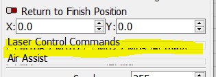
Currently I don’t see those options in the menu. From the post I found I may need to expand the window or change the aspect ratio of my screen to see it.
Trying to get all the firmware changes made to my current build before I compile it. The list is getting bigger by the day.
With the Settings dialog open, drag the corner to resize the dialog, and the commands will appear.
The area in yellow is the part you want to get to display. I did not have this problem when I originally started to use Lightburn, but it creeped in during one of the upgrades. Since it has not been fixed over several upgrades, I’m assuming it only happens for specific Windows screen settings/resolutions.