Prototype/v1/Alpha
This is a long time coming, it took a while but here we are! I have already started working on v2/beta by reducing the height of the probe to about 52mm but I do think I can go a bit shorter if people think that it should be. I have ordered some custom pcbs for cheep to try out my old circuit design which you can see sitting in the picture of the probe I attached (Pictures 4-7). This is not what I am going to be using going forward, and the new circuit I have designed takes into account the current over the probe to negate oxidation on the contacts between the balls and the pins but still have enough current to make the connection reliable. After some research I ended up with about 5ma (Let me know if this is not right). I have added two LEDS, one that is green that displays power and is constant on (Pictures 2-3). The other is a red LED and it is triggered by contact with an object visually signaling a touch (Picture 3). The LEDS I used are Adafruit sequins and have a 100 ohm resistor baked in to them so that had to be taken into account when designing the circuit. If anyone finds and mistakes or has any improvements they think would benefit the circuit design please don’t feel afraid to chime in  . All 3d printed parts are printed in Prusament PETG on a mk3s at 0.2 layer height and 20-40% infil. Since this is a alpha/prototype/v1 i’m not going to include the STL’s but if you want them please send me a message or comment that you want them and ill send them over. I have a 50mm ruby tipped stylus that is arriving any day now that I am excited to attach and work with!
Circuit Design
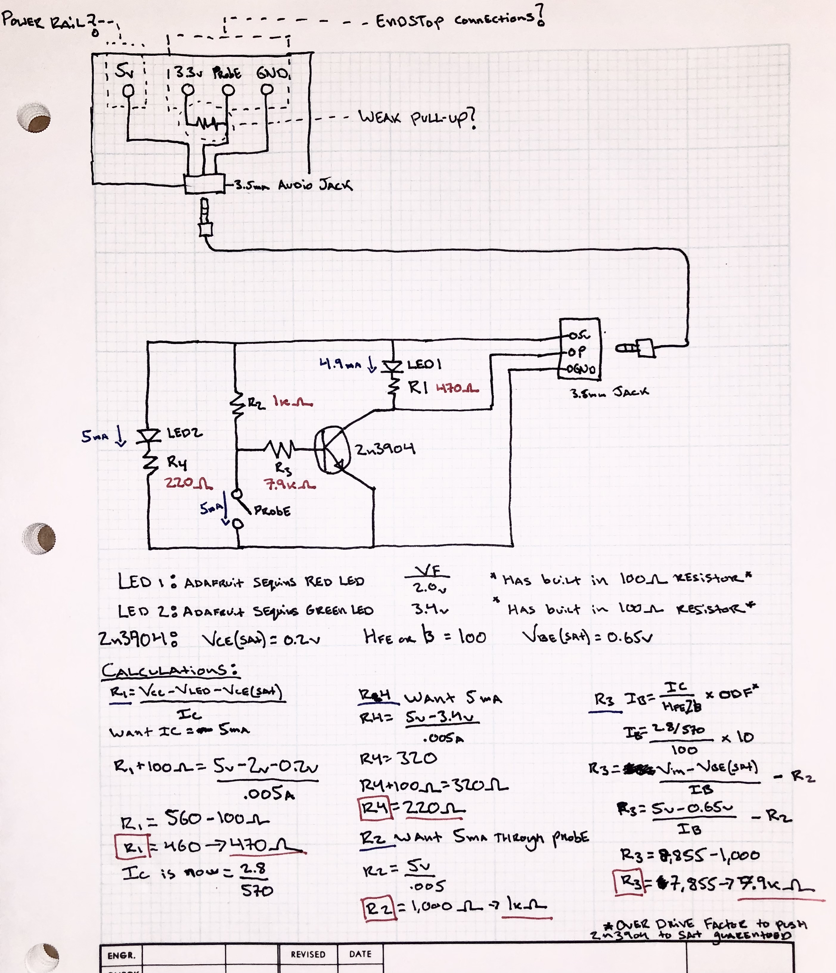
(Picture 1)
Testing Circuit on probe
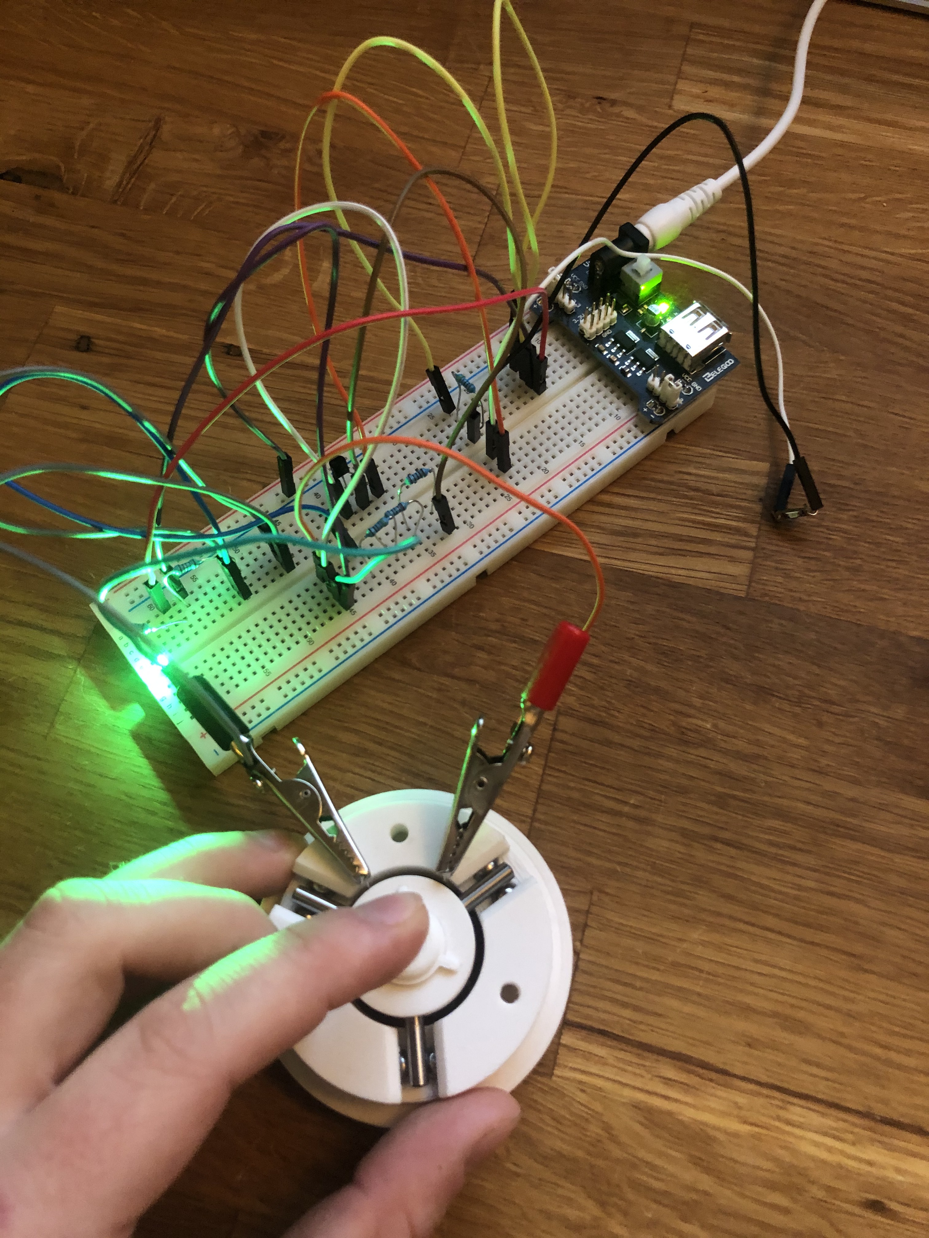
(Picture 2: Probe is closed and not triggered)
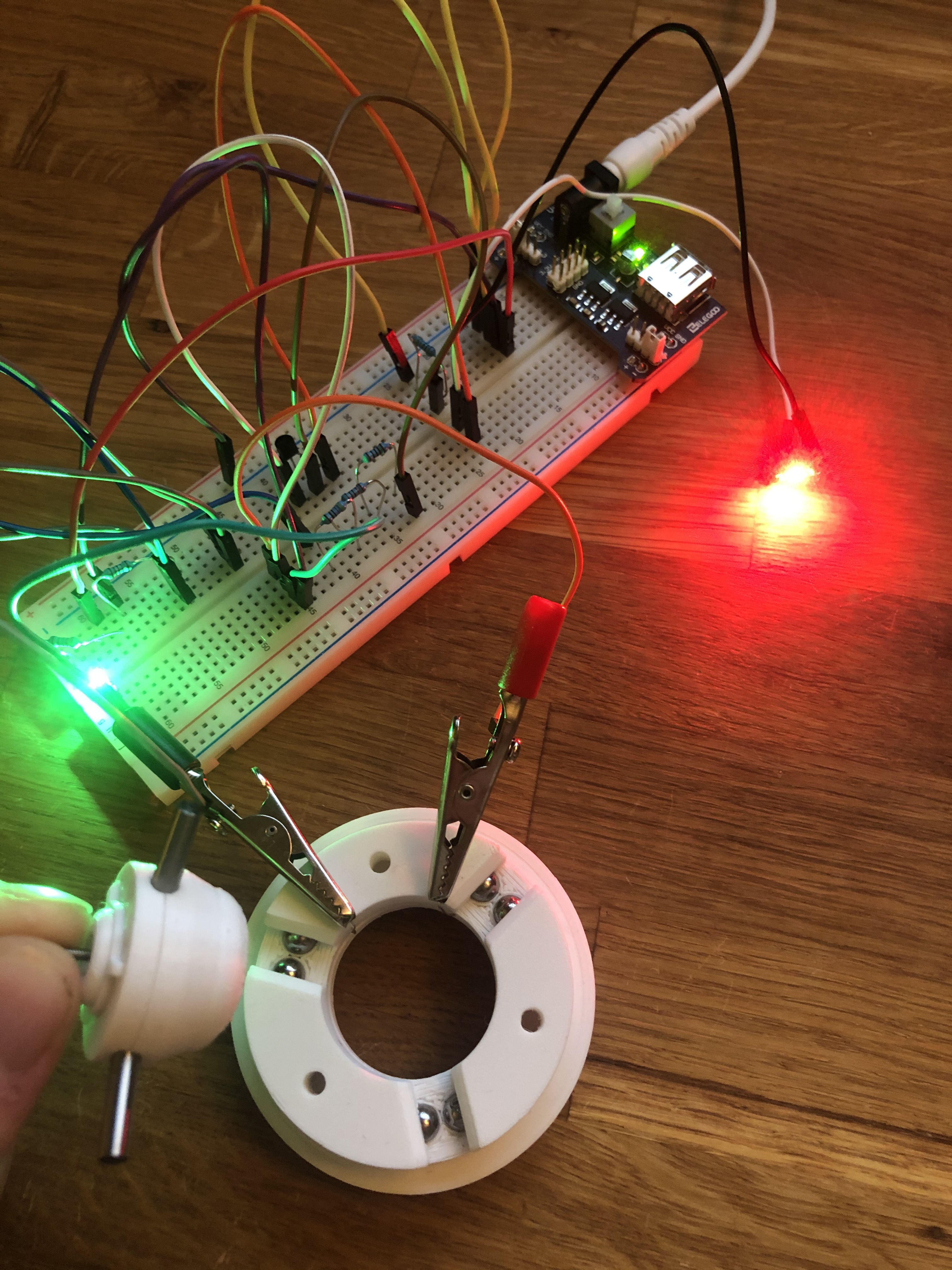
(Picture 3: Probe is open and is triggered)
First Prototype
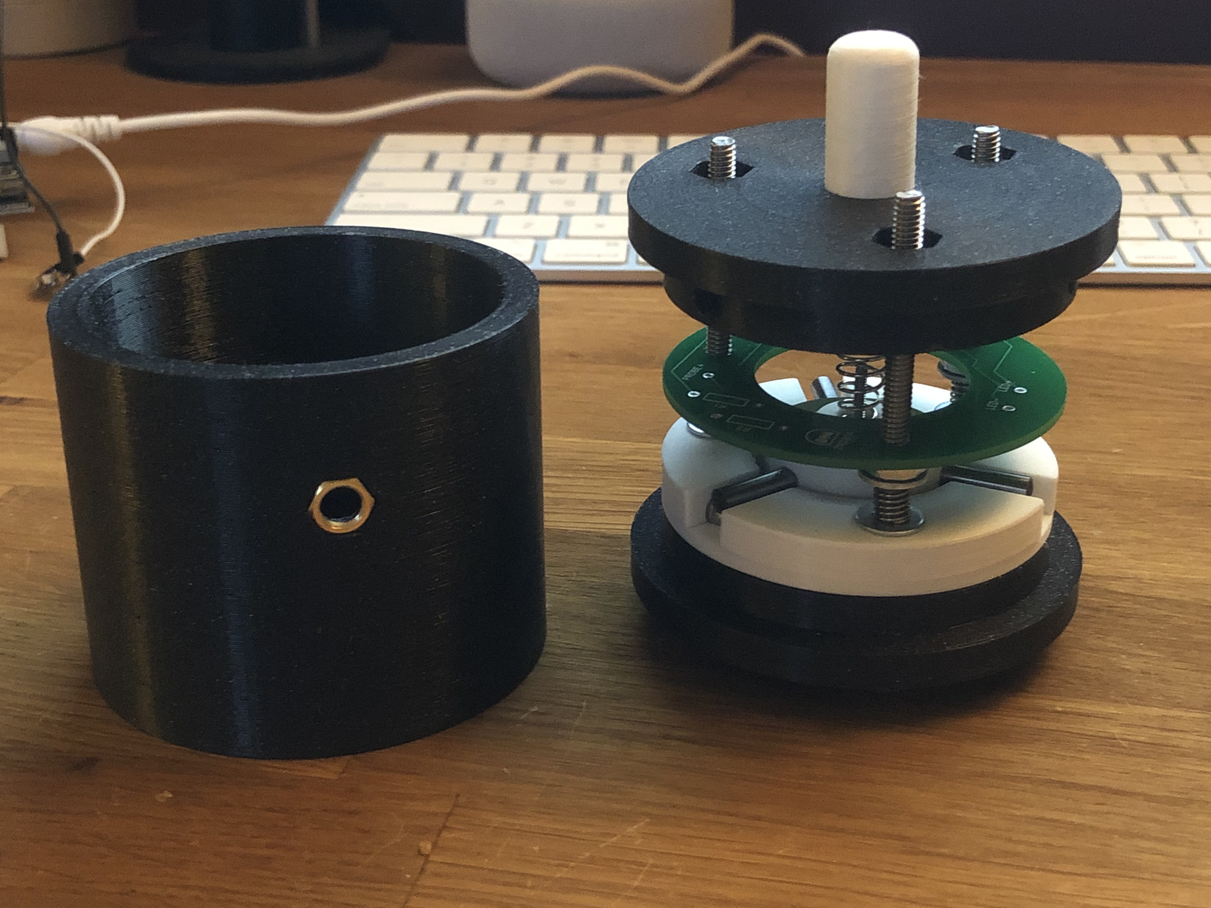
(Picture 4)
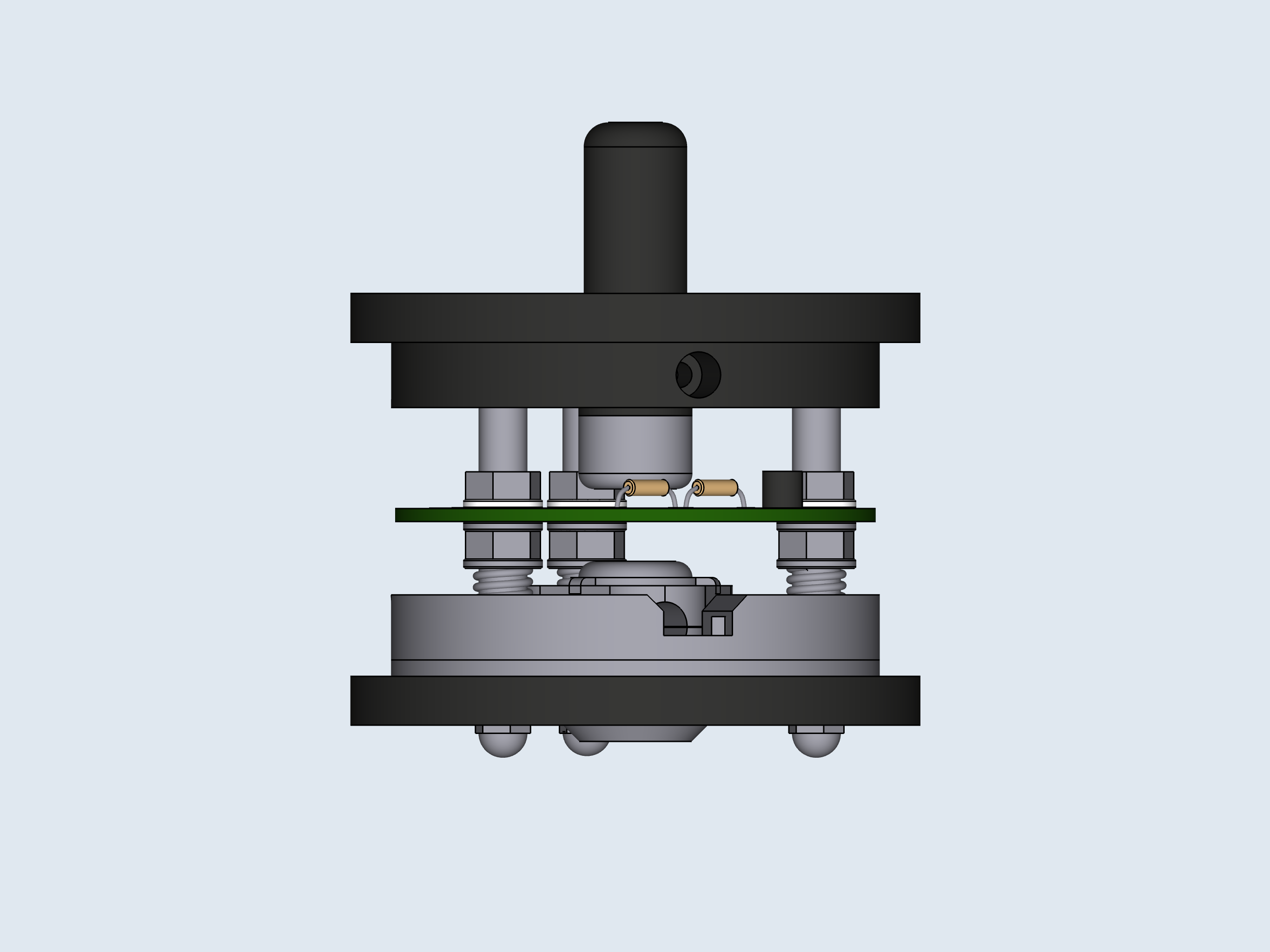
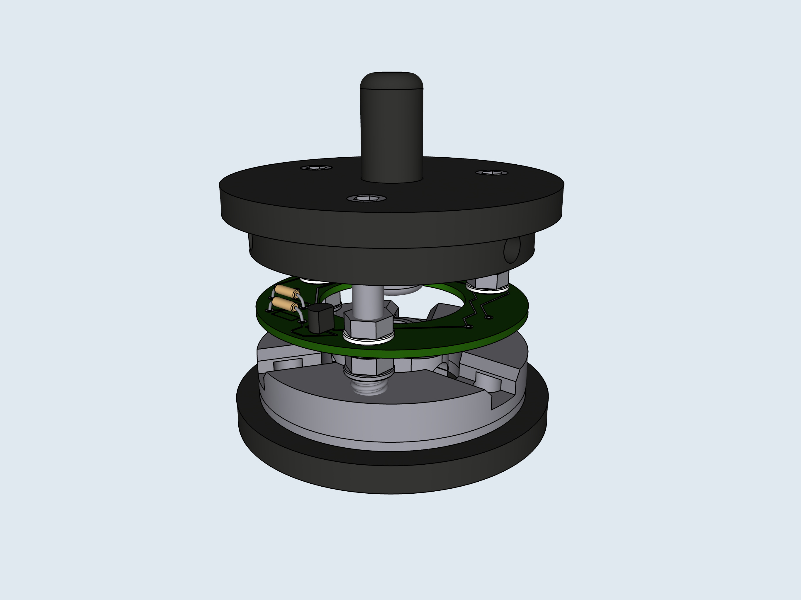
Models of prototype
These are models of the prototype that I am using to create my STLs and to design around. These do have some v2 improvements added to them (I apologize). The changes in these models from the prototype are the reduction in height, change in the ball carriers and pin carriers, and changes in the bottom plate. In picture 7 you can see three empty holes on the underside. These holes are for small m2 or m3 screws (haven’t decided yet). The screws are to make fine adjustments to the ball carrier plate so that one can truly center the probe if for some reason it is not already centered or the probe tip you are using is off.
(Picture 5)
(Picture 6)
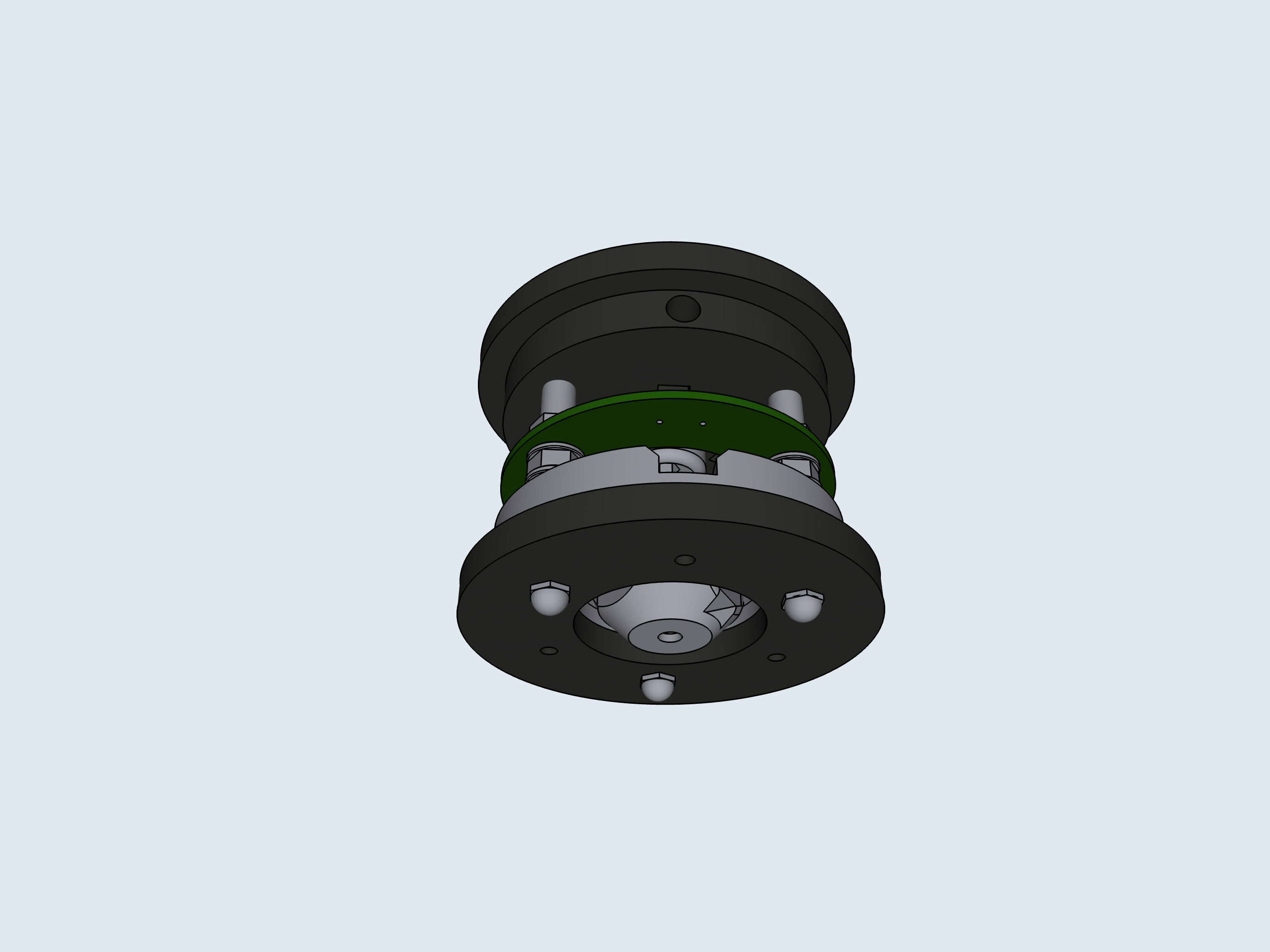
(Picture 7)