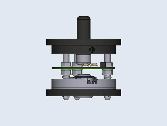
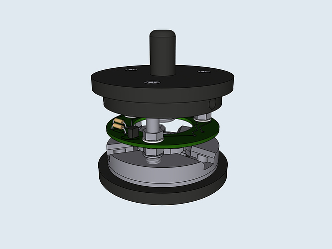
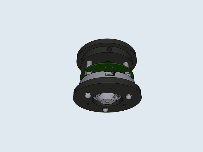
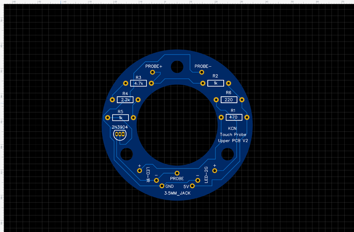
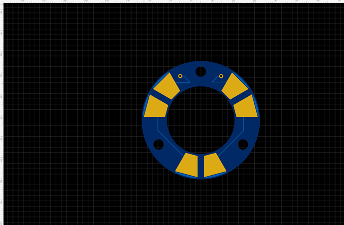
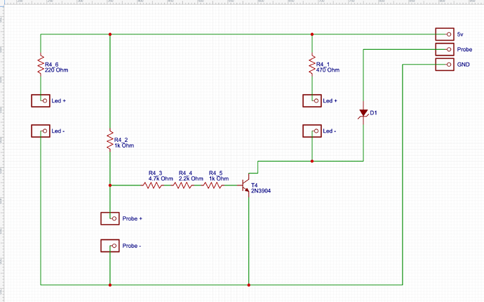
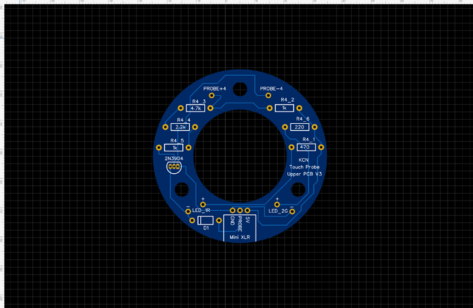
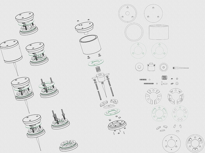
Howdy! I am designing a 3D Digitizing Probe to be used with my hopefully soon to be built lowrider2. I did some looking around for a cheep 3D digitizing probe but had no luck finding a good cheep option. After seeing some people’s attempts to build their own DIY Digitizing Probe I thought to myself, why not give it a shot while you are waiting. I looked at a few of those attempts and tried to make something of the sort of best of both worlds and this is what I quickly came up with! What I still need to finish is the top circuit board and a port for a wired connection seen started in the top left assembled markup and possibly some LEDs to give visual feedback while in action. Let me know what you think about the design and give some feedback what changes I should make! If you have any pointers, recommendations, or lessons learned if you have tried making one of these please let me know as well!!!
Little info:
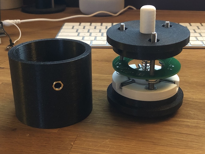
Minus the rods that sit on ball bearings, circuit board, probe tip, wiring, screws, and springs, everything else is going to be 3D printed.
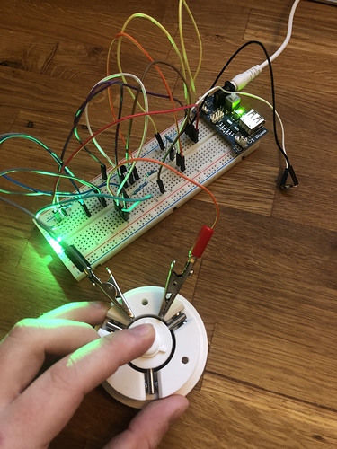
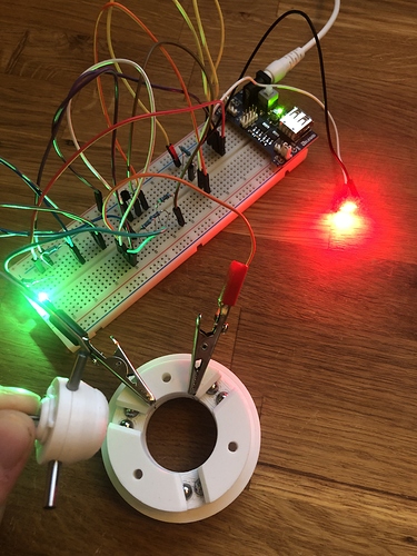
How this works is that a current is fed into one end of the circuit containing the ball bearings. The three metal rods coming out of the center hub sits on top of these duel ball bearings and completes the circuit. When the probe comes into contact with an object the rods or rod will lift and thus not be in contact with the ball bearings it sits on, breaking the circuit.
I plan on using three screws from the bottom that push on three small plates underneath the three sets of dual ball bearings so I can fine tune the accuracy of the probe.
Three springs which surround the three structural screws that keep the device together are in constant contact with the top of the ball bearings structure keeping everything in place and pushing the object down towards the leveling screws I just mentioned. This should cheaply allow for some decent fine tuning (hopefully, that’s the plan at least ).
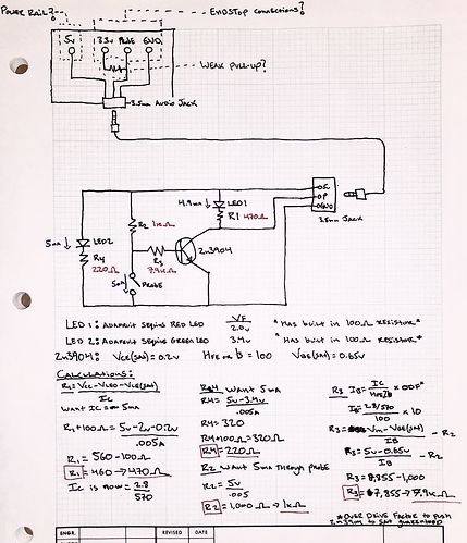
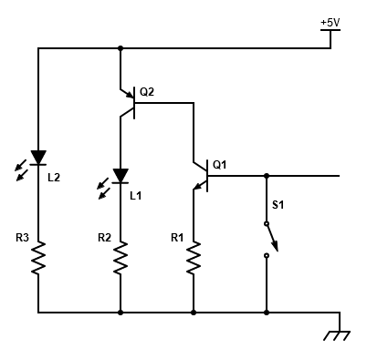
I haven’t drawn it yet but I’m thinking of placing on the top circuit board a circuit that inverts the signal so that instead of constantly feeding 5V to what ever is driving this, that it only sends a signal when contact is made.
I have read that after quite some time, having power run through the circuit and doing tons of contacts, that as the metal probes lift off the ball bearings, it may arc slightly causing an oxidizing layer that can effect the performance of this. Ive also read that when this happens, all you need to do is brush off that oxide layer and it will work just like new again? Not too sure about this but if anyone could give me some info on this I would greatly appreciate that!
I haven’t decided on how im planning on mounting this to the cnc but more than likely I will incorporate some type of easy tool changer so I can just place this inside the bit and not have to find a way to mount and find the offset and everything else involved with that.
Any ways, hope someone found this interesting or has some great feedback on this design for a 3D Digitizing Probe that I’m planning of incorporating into my cnc!
 try and make the board so we can cnc it too double bonus

