Hallo,
Ich habe mir vor ein paar Wochen eine mpcnc gebaut. Diese ist aber etwas anders als das original. Ich habe den Spindelhalter auf Alu umgebaut. Wie hier im Bild zu sehen. Das Grundprinzip ist aber gleich. Mein Problem ist aber folgendes. Wenn ich zum Beispiel meine x Achse einstelle/abgleiche mit einer Messuhr auf 5mm, dann werden diese exakt angefahren. Wenn ich aber 9mm anfahre hab ich 0,4mm mehr. Umso mehr weg ich fahre umso größer die Abweichung. Fahre ich aber Beispielsweise die 9mm wieder zurück lande ich wieder auf 0. Bei Fräsvorgängen kommt es dann zu Abweichungen, beispielsweise 4 Taschen 10mm breit und 5mm Abstand dazwischen kommen nur mit 9,7breit und einem Abstand von 6,7mm raus. Ich bin langsam am verzweifeln. Ich verwende ein cnc shield v3 mit einem arduino v3 und estlcam installiert. Post-process mit Fusion 360.Verbaut sind nema 17 Motore mit drv8825 treibern. Als Netzteil verwende ich eins mit 12v 30A und 360W. Ich habe auch geschirmte Kabel verwendet. Hat jemand eine Idee wie ich das ganze eingrenzen kann?
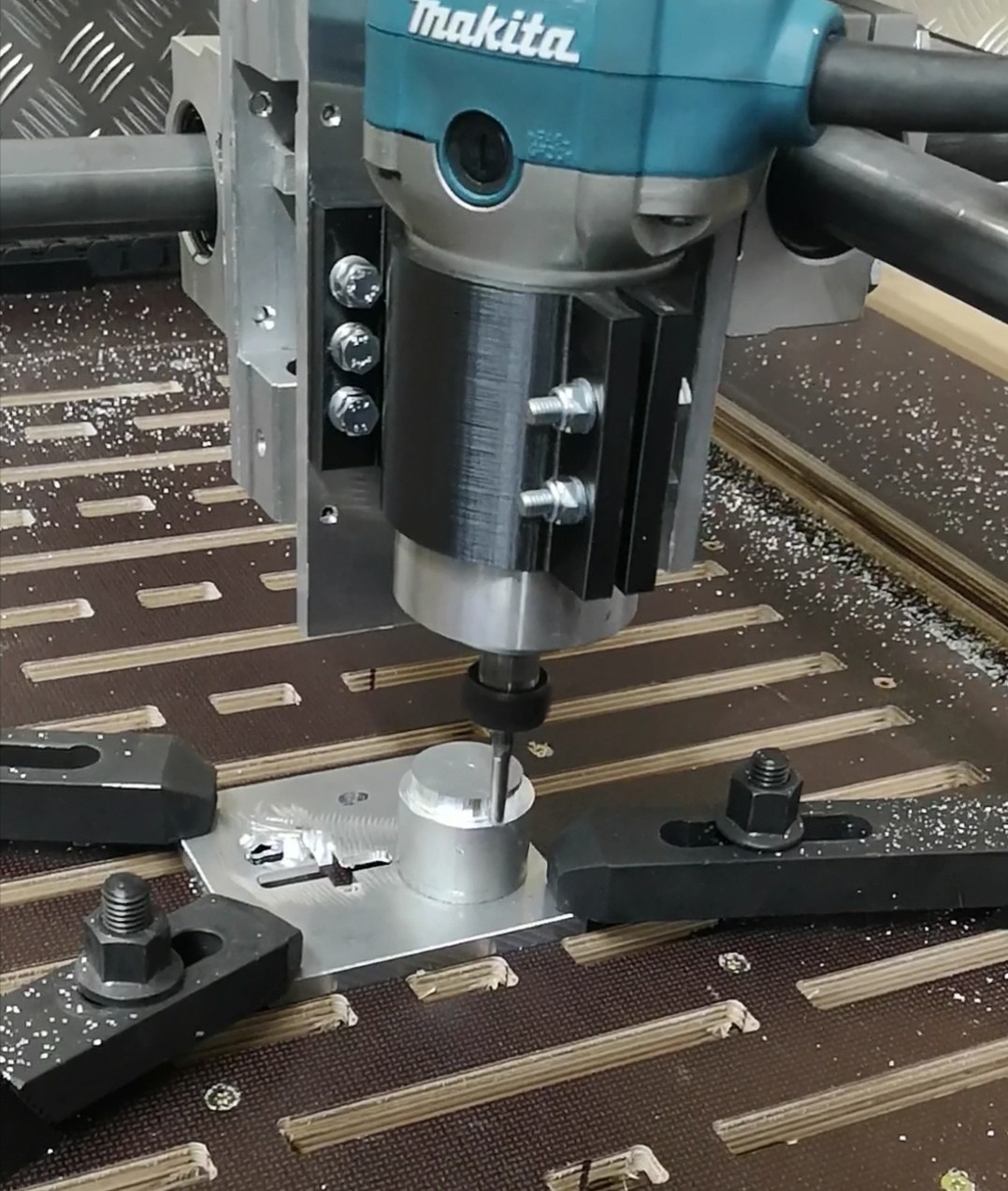
I built a mpcnc a few weeks ago. But this is a little different from the original. I converted the spindle holder to aluminum. As seen here in the picture. But the basic principle is the same. But my problem is this. For example, if I set / adjust my x axis to 5mm with a dial gauge, then these are approached exactly. But when I start 9mm I have 0.4mm more. The more away I drive, the greater the deviation. But if I go back, for example, the 9mm I land again on 0. During milling operations there are deviations, for example 4 pockets 10mm wide and 5mm between them only come out with 9.7 wide and a distance of 6.7mm. I’m slowly desperate. I use a cnc shield v3 with an arduino v3 and estlcam installed. Post-process with Fusion 360, nema 17 motors with drv8825 drivers are installed. As a power supply I use one with 12v 30A and 360W. I also used shielded cables. Does anyone have any idea how I can narrow it down?
I’m having a bit of difficulty understanding your problem. It may be due to the google translation. Have your verified your steps per mm? Pick an arbitrary origin. Without running the router, lower the bit until it marks the spoil board. Send the router to a specific distance on the X and the Y. Mark the board again.
Measure the result. If the physical distance does not match the distance you commanded the router to move, you need to track down the cause. It could be because you used a different pully than the one V1specified for example. Or that you have used steel reinforced timing belts that have broken internally and stretched. Steel reinforced belts fail fairly quickly on the MPCNC. If it is a pully issue, you can fix it using the M92 g-code to adjust the steps per mm for your machine.
If your travel distance is accurate, but your holes are too small, then there are a whole other set of steps to take.
Google translate:
Ich habe ein bisschen Schwierigkeiten, Ihr Problem zu verstehen. Dies kann an der Google-Übersetzung liegen. Haben Sie Ihre Schritte pro mm überprüft? Wählen Sie einen beliebigen Ursprung. Senken Sie das Bit ab, ohne den Router zu betreiben, bis es die Spoil Board markiert. Senden Sie den Router auf eine bestimmte Entfernung auf dem X und dem Y. Markieren Sie die Karte erneut.
Messen Sie das Ergebnis. Wenn die physische Entfernung nicht mit der Entfernung übereinstimmt, die Sie dem Router zum Bewegen befohlen haben, müssen Sie die Ursache ermitteln. Dies könnte daran liegen, dass Sie einen anderen Pully als den von V1 angegebenen verwendet haben. Oder dass Sie stahlverstärkte Zahnriemen verwendet haben, die innen gebrochen und gedehnt sind. Stahlverstärkte Riemen versagen beim MPCNC ziemlich schnell. Wenn es sich um ein Pully-Problem handelt, können Sie es mithilfe des [M92-G-Codes] (Set Axis Steps-per-unit | Marlin Firmware) beheben, um die Schritte pro mm für Ihre Maschine anzupassen.
Wenn Ihre Reisedistanz genau ist, Ihre Löcher jedoch zu klein sind, müssen Sie eine ganze Reihe weiterer Schritte ausführen.
Hast du Endschalter verbaut? Dann könntest du mit Estlcam eine Referenzfahrt machen, danach im Eilgang etwas hin und her und anschließend wieder eine Referenzfahrt. Estlcam kann dir dann ermitteln, ob deine Stepper Schrittverluste haben.
Das würde die Ursache schon mal eingrenzen
Thanks for your fast answer! If I set x to 0. After that I let the x-axis go to 5mm. That’s correct, exactly 5mm. Let it drive back to 0 is perfect too. But if you go from 0 to 9, it stops at 9,4. If you go higher than 9 the more is the failure.
Danke Rich, gute Idee. Werd ich morge mal testen!
If you start the origin of your measurement at different places on the spoil board, do you have exactly the same problem? Is it only one axis, or both axes? And just to verify, you can always return to the same origin if you reverse the move no matter what the distance? If the problem is consistent, can give us a list distances and measurements: 5, 10, 20, 30, 40, 80, 150?
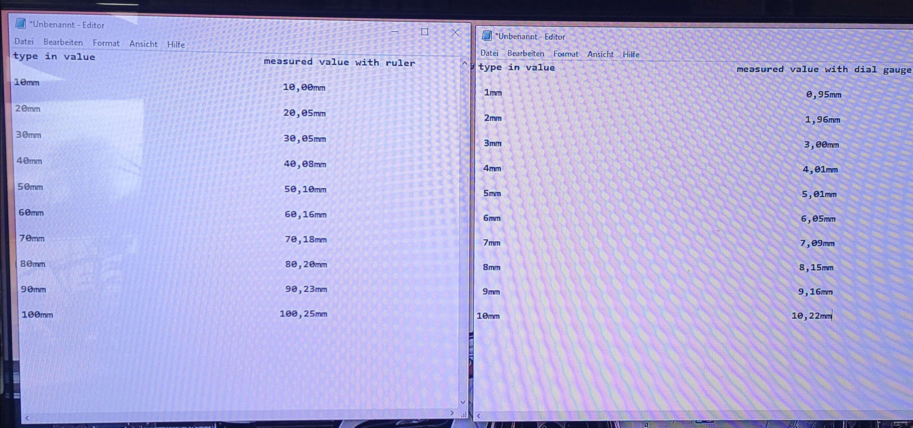
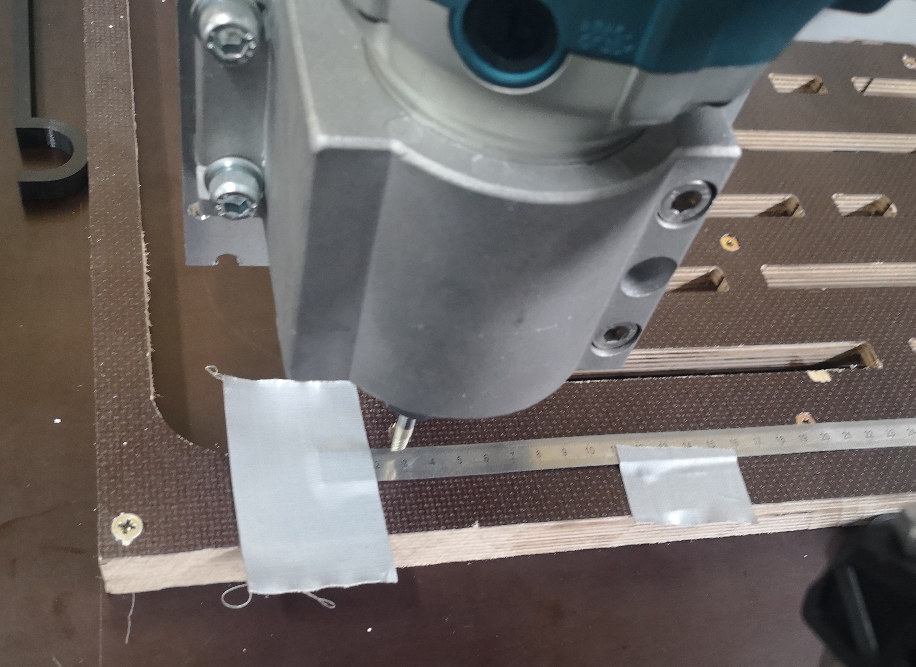
I made my homework. I measured at the left and right corners like in the picture with a ruler. Not that accurate but you get an idea. It’s always the same in every corner. But you will always get back to 0 point. So if you type in 10 it gets physically to 10.22 but if you type - 10 you are physically again at 0.
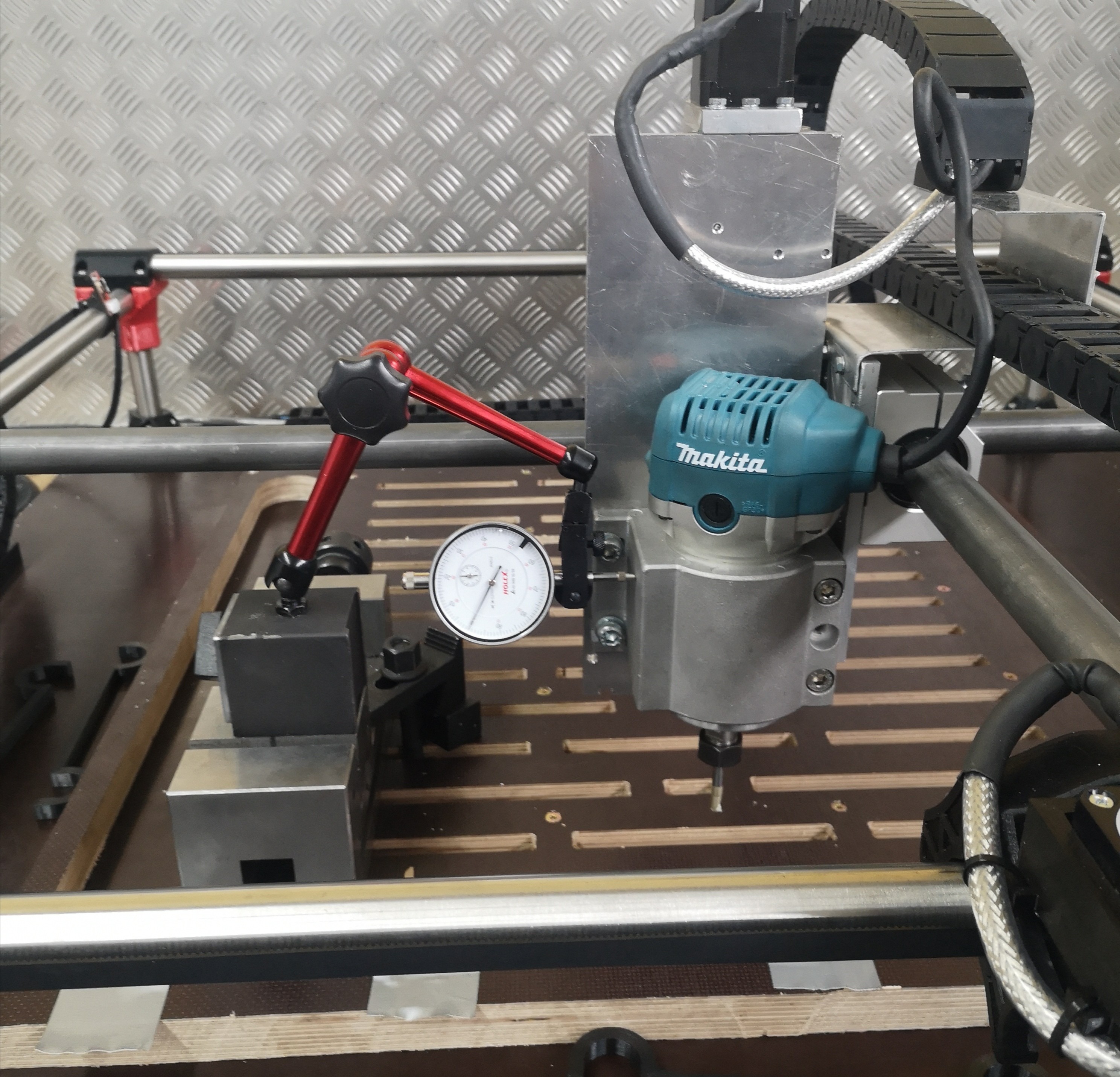
I checked stepp loss with the home function. X= 10 stepps/0.19mmm and y= 10 stepps/0.19mm. I did that a few times. Worst one was x=21stepps/0.41mm and y - 9/-0.17mm. There are no switches at the Z axes. I also tried different speeds at the measurements but always the same.
I checked y-axis and it is exactly the same values.
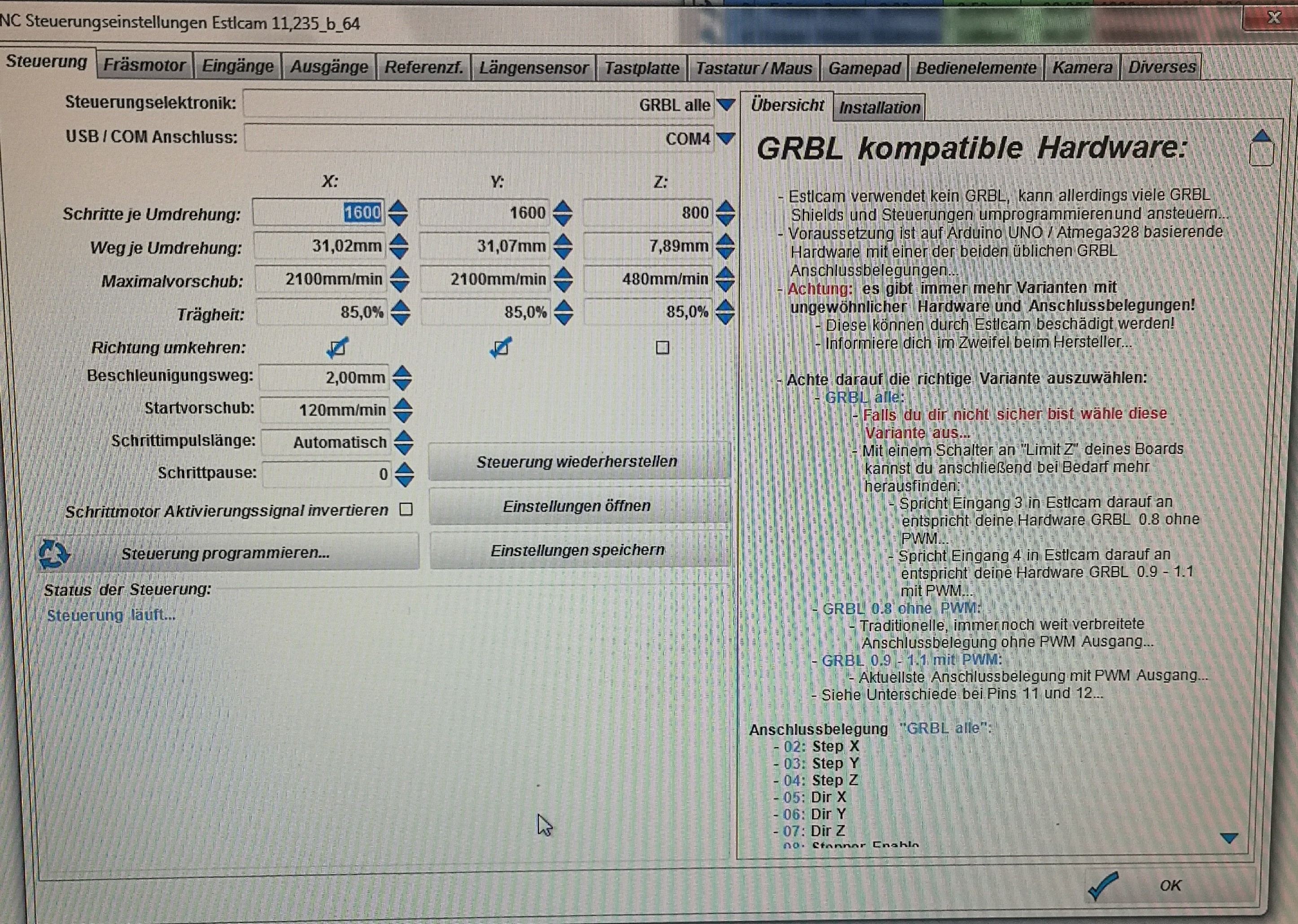
What is the 31,02mm number? (Sorry, I don’t know estlcam firmware well enough or German enough to tell). I feel like that should be a round number. Maybe mm/rotation? Should be 32.0.
It doesn’t look like a very good scaled value. The 100mm is off by 0.25% and the 10mm is off by 2.2%. if you change the steps/mm, one of those is going to be off by 2.05%.
It also seems strange that the dial measured a 0.22mm error at 10. But the ruler didn’t measure any error at 10. I thought maybe it was the precision of the ruler (or the ruler reader) but you reported 0.25mm error later.
I’m with Jeff. With 2mm GT2 belts you should not have to tune in the distance per revolution.
Please set it to 32mm. If you get small or big dimensions on your workpiece, that might be related to different things like belt tension or so…
Please also increase your acceleration distance to 5mm at least and perhaps lower the acceleration speed to 60mm/min. I think your steppers are loosing the steps at acceleration
I changed the values as you wrote Rich and it’s way better than before. I didn’t have the time to make a test the next 2 days but I will on Monday and give you feedback. I quickly measured again with the ruler and you get what you type in.
Thanks a lot and enjoy your weekend!
If you don’t mind me asking, where did you get the original values? Maybe we have some documentation upstream we need to fix.
I have watched a video on YouTube. To make fine adjustments you have to take a dial gauge, type in 5 on x or y axes at estlcam, measure the physical way for example 4.8. Than 5:4.8=1, 04mm. 32:1,04=30,77mm. That’s what I did. Didn’t worked that well for me I think.
Interesting.
The error comes in two flavors. Backlash and scalar. Backlash is if you move to 0 from the left or from the right, you will get different values. It kind of looks like (from the 1mm dial number) you had about a 0.05mm backlash. That comes from things like the teeth on the gears not meshing perfectly with the belt, or something being loose or just flexing. Every system has some number of backlash. 0.05mm is NBD.
When you measure 10mm or 5mm with a dial, and you are trying to measure the scalar error though. That 0.05mm backlash can really mess with a 5mm measurement. So if even though your dial is very accurate, it is probably still better to measure something like 400mm (or however long you can) with a ruler or even tape. The backlash and ruler accuracy are going to be much smaller at 400. Because measuring 2mm is easy, measuring 0.2mm is hard (especially with backlash).
I’ll also tell you that running at 32 is generally my advice (well, running at a round 100 or 200 steps/mm). Then larger errors in backlash or scale are more obvious. It sucks to calibrate a broken belt at 400mm and have the 80mm workpiece be wrong. The pulley has exactly 16 teeth, the motors and drivers have exactly 1600 steps/rotation (never 1599 or 1601). The only flexible part is the belt and they are reinforced to avoid stretching (and they do a good job at it).