High Z Mod Lowrider 4 – 250mm for taller bassrelief

Hi everyone! :raised_hands:

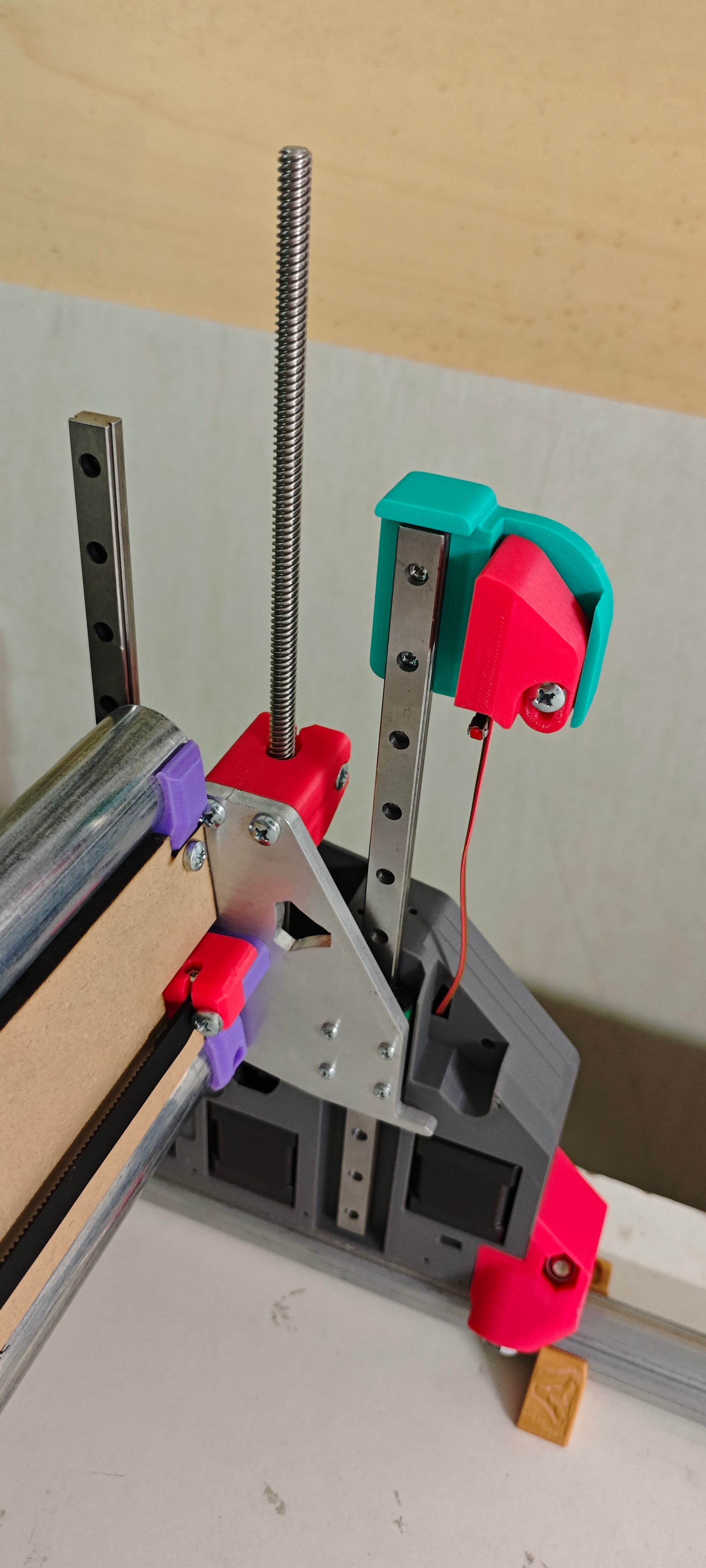
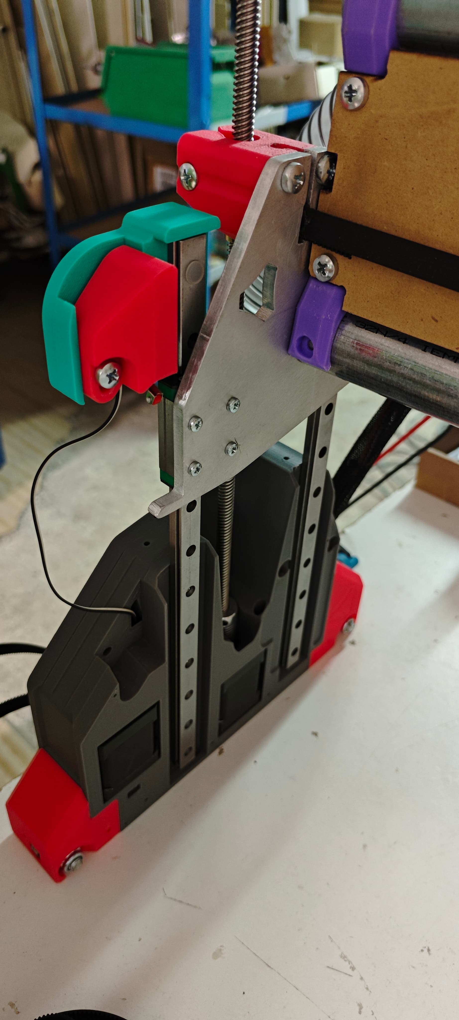
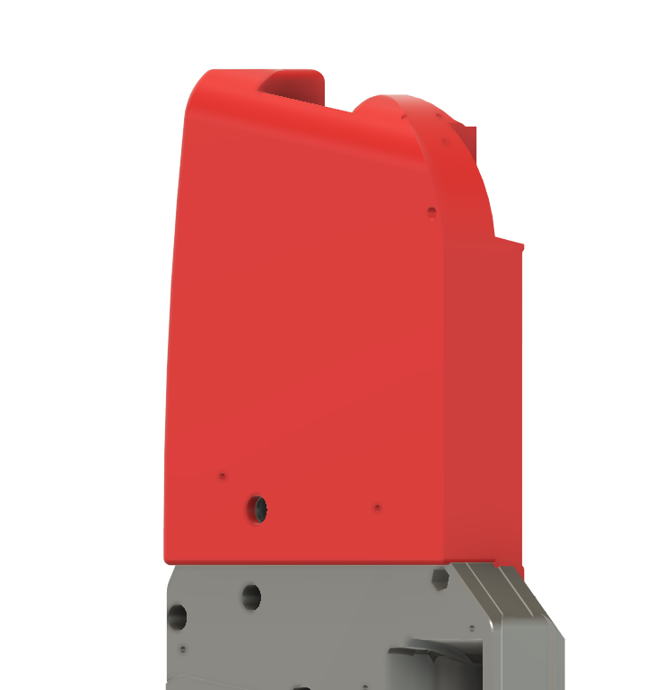
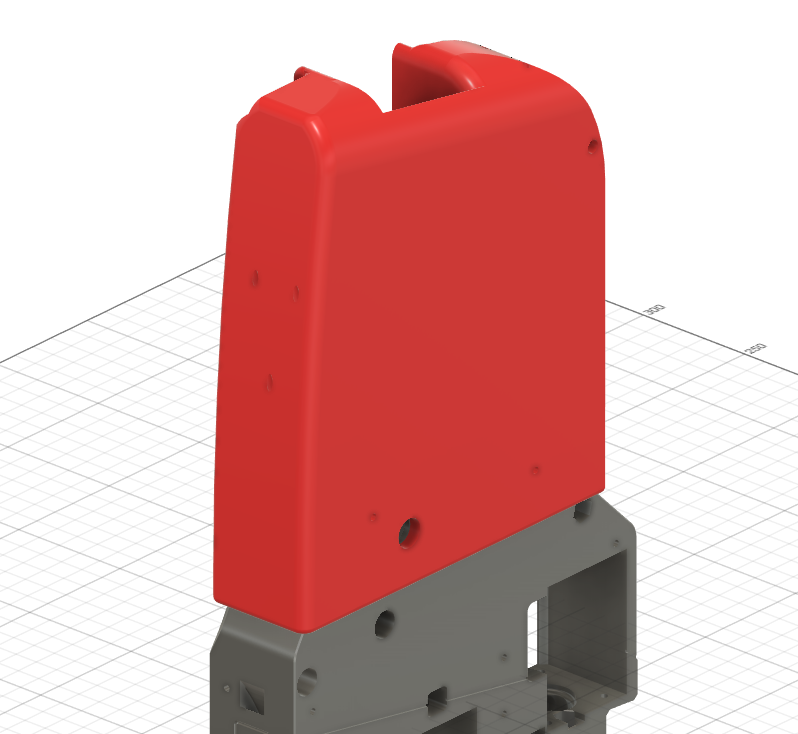
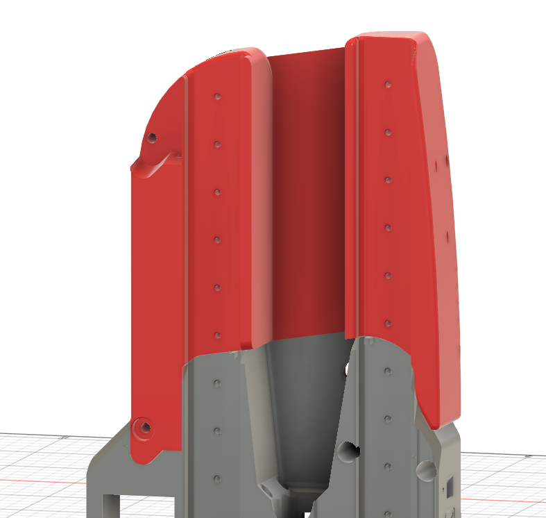
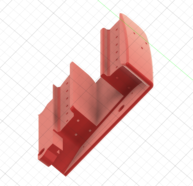
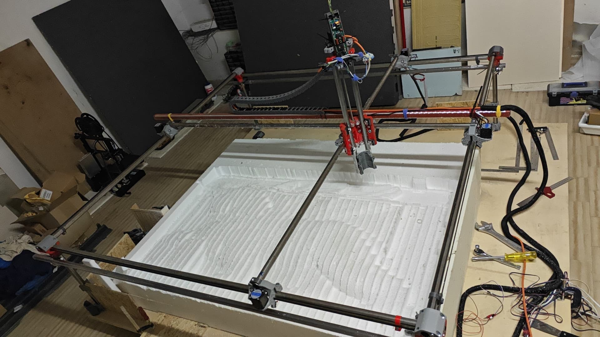
I’ve been working on a Z-axis extension for the LowRider 4 CNC, mainly to increase the vertical travel for working with tall foam and polystyrene blocks.

By replacing the original 150 mm linear rails with 300 mm rails (11.8"),
I was able to get around 250 mm (9.8") of Z travel, which is great for my use case (soft material + long tools up to 200 mm / ~8").
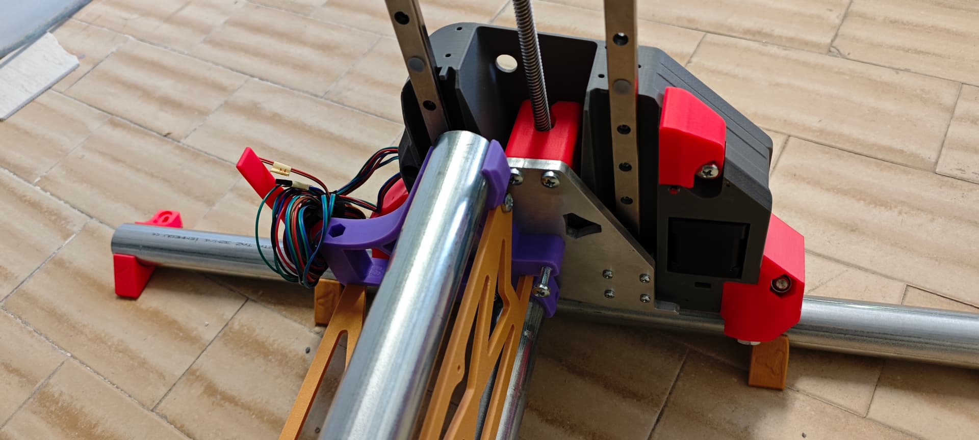


:warning: I know the LowRider works best when it stays low – rigidity matters!
But for foam work, it’s not a big issue, and this gave me the flexibility I needed.

To make the most of this added height, I also working on a drop table with adjustable height: I can lower the work surface depending on the thickness of the material, keeping the gantry rails at the same level and improving tool access without sacrificing too much Z rigidity.
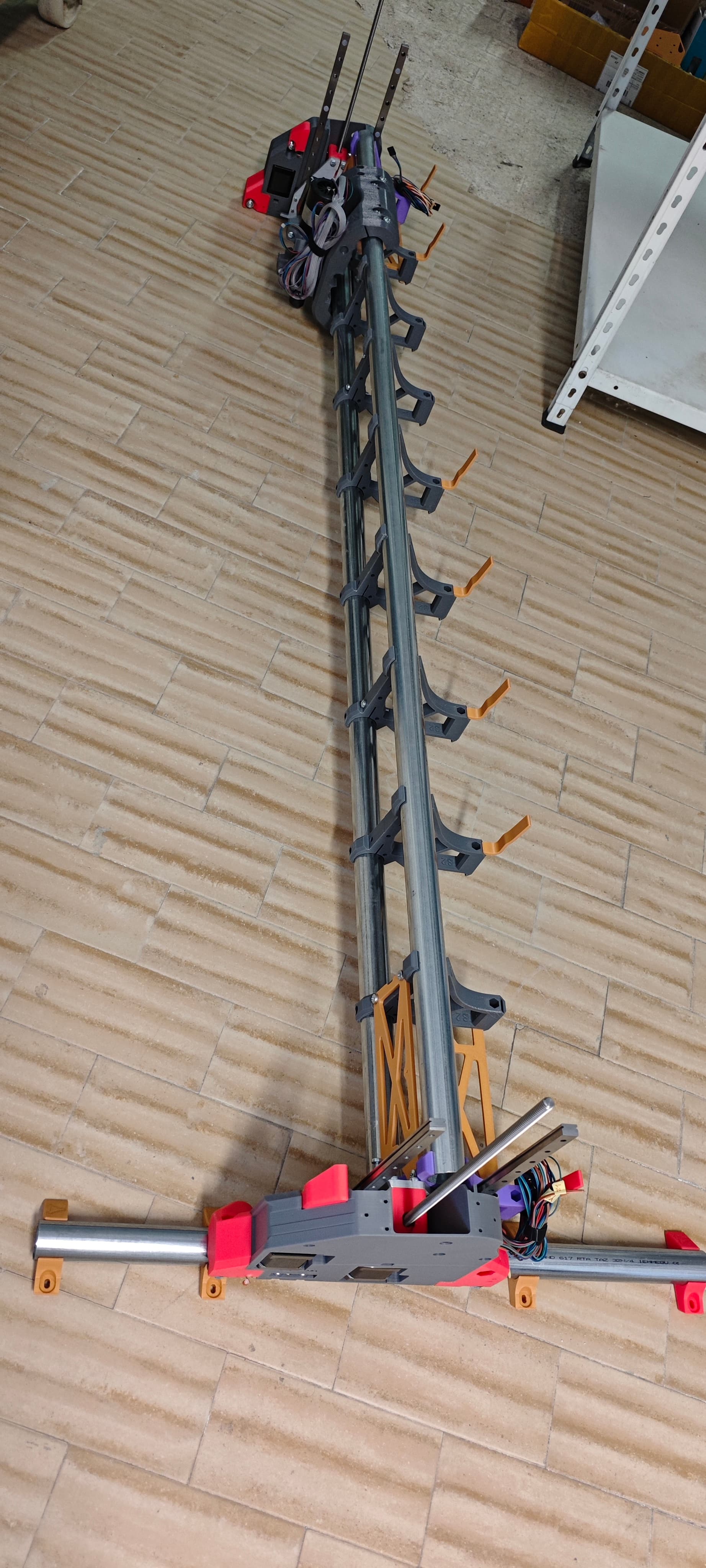
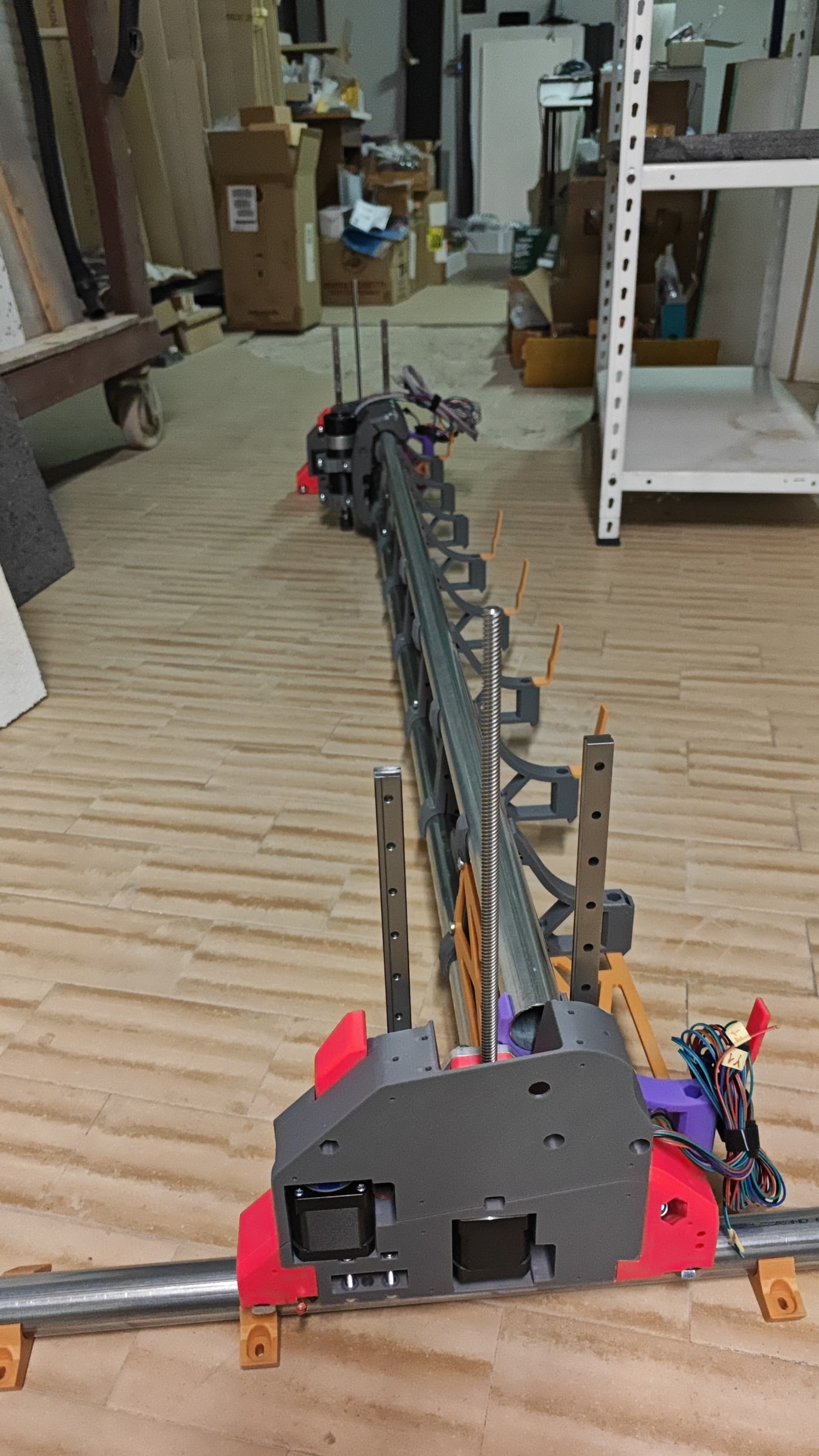
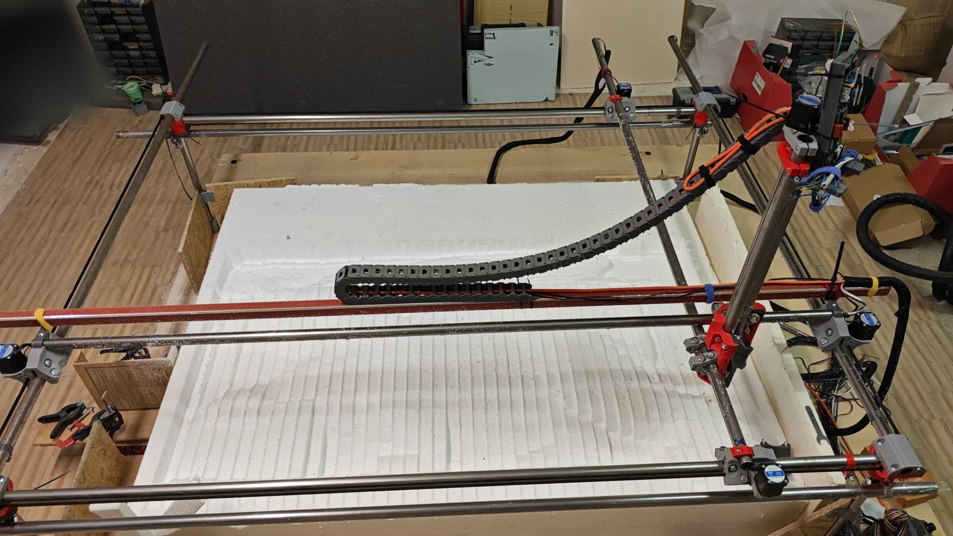
:hammer_and_wrench: I built my LowRider V4 with an X working width of 1500 mm (~59") and a Y length of 3700 mm (~145").
The machine is assembled and ready, but I still need to finish building the custom table — it will include the adjustable drop-surface mentioned above.


:speech_balloon: Backstory:
I previously tried building an oversized MPCNC Primo (1500 x 1500 mm / 59" x 59") with a Z height of 400 mm (15.7"). It looked amazing, but after a short time, the X-axis began skipping steps and started moving asymmetrically and in jerks. The build was just too large and flexible for my needs.

VIDEO LINK: first time hot rigid wire cutting Video


VIDEO: hot rigid wire first cut

VIDEO: First parallel milling cut with 200mm bit tool and 55mm 600W router


So now I’m testing the LowRider V4, which seems more suited for bigger format CNC work.
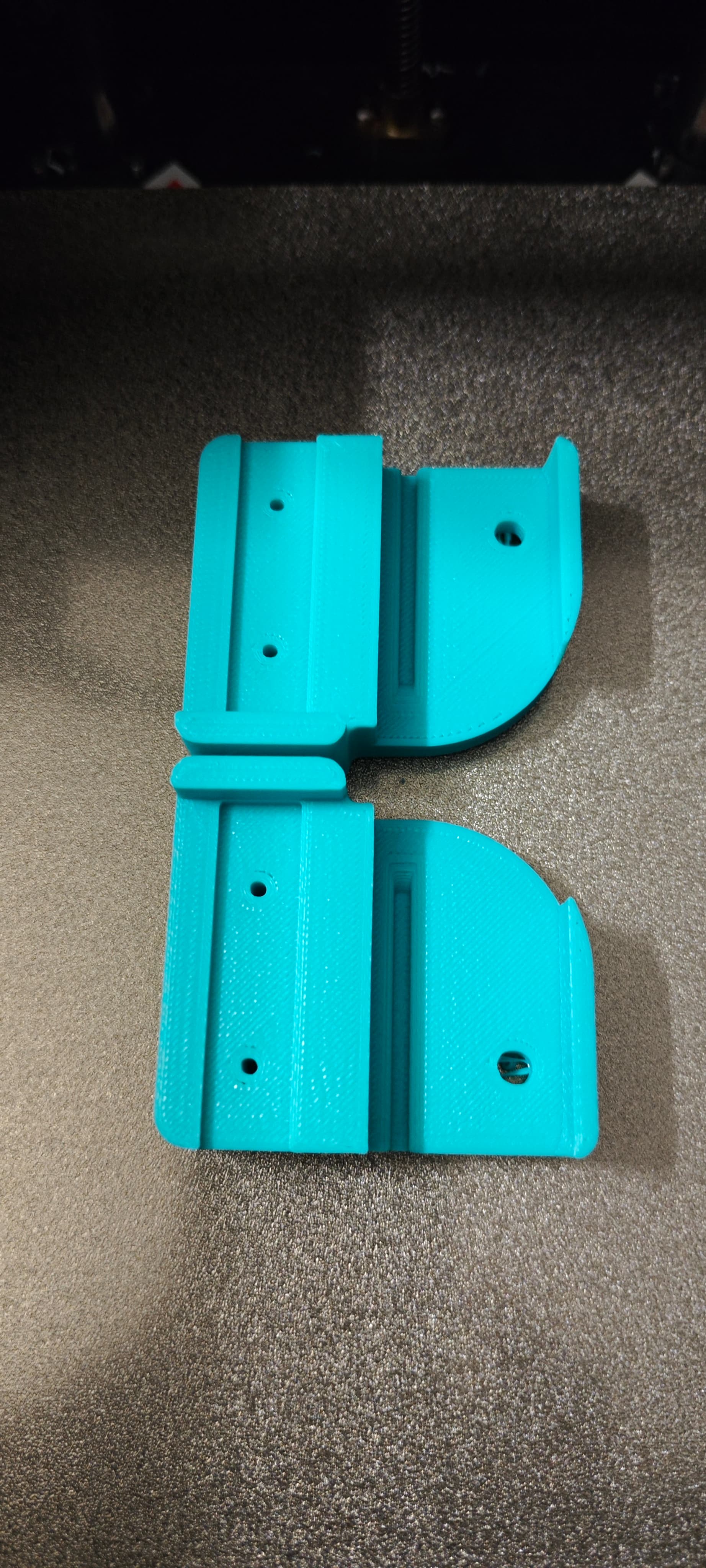
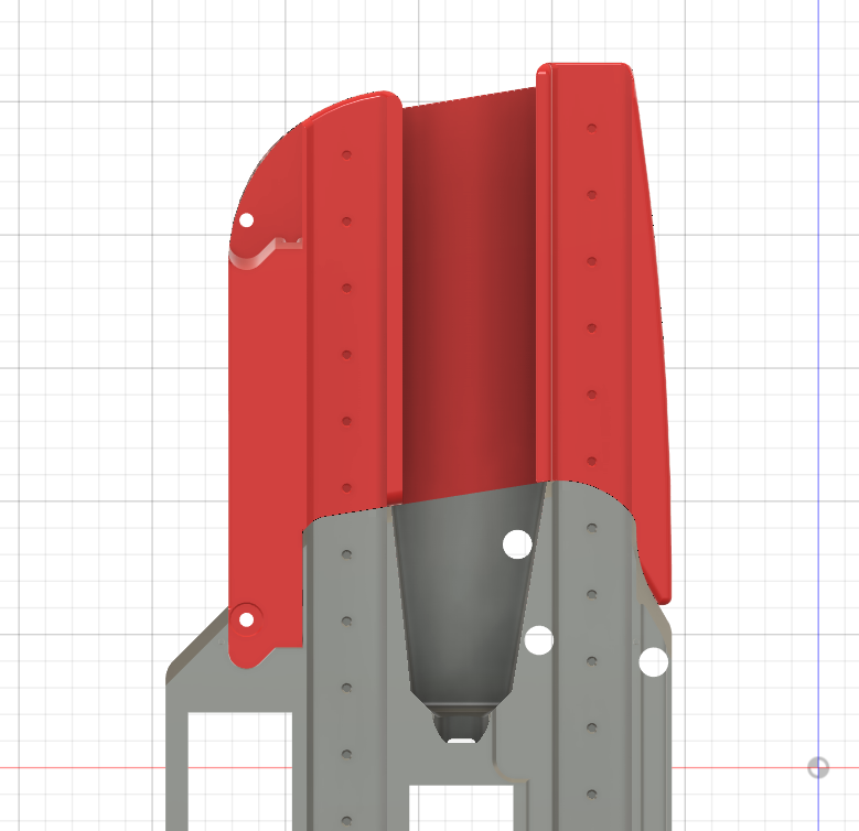
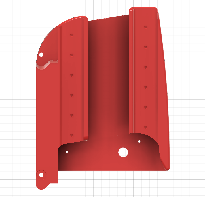
:repeat: I only had the original YZ_Plate_Min_V1.stl https://www.printables.com/model/1034840-lowrider-4-cnc/files STL file available, and had to work around some limitations in Fusion 360 ( negative XYSTEP files wouldn’t import cleanly). So I did my best but I’m actively looking for help to improve, optimize, simplify or even rethink it entirely if needed.


:hammer_and_wrench: Suggested print details:

– Requires minimum print bed of 210 mm
– minimum supports needed
– PLA or PLA+ recommended
– Layer height: 0.2 mm
– Infill: 15–20% sufficient

:paperclip: Printables link: printables file


:busts_in_silhouette: Call to action:
If you’re interested in this kind of mod, or just curious, I’d love to hear your thoughts.
If you want to help improve the design, adapt it for other sizes, clean up the geometry, or even just discuss possible implications I’d be super happy to collaborate.

Thanks V1Engineering and V1 community for being an inspiring place to build and share!
Greetings from Italy
Mirko

11 Likes

Interesting mod! If you’re building a custom table for a specific Usable cutting area, and planning lots of tall cuts, then, before committing to specific table, consider doing some testing to figure out how stable machine will be along the Y axis. Depending on many things, am wondering (after chatting with Jim, Ryan, Barry at RMRRF) if a very tall machine will benefit from extending the Y footprint (E.g. bolt on Y stabilizers or use modded elongated wheel/roller parts).

2 Likes

I rebuit my lr3 to a highrider0.1… I’m am defenitely going to look into you rigid hot wire cutter!
I’m trying to source some time to build the LR4 now, I’m trying to get my son involved in building and it seems to work. I’m not planning to make the LR4 taller, but i’m going to follow this topic!

1 Like

@Mirkoferronato this looks like interesting idea, I have been using my lowrider to cut foilboards which are 8-9" thick and was looking for ways to extend my Z. Would love to give your mod a try but it looks le the printables link only has the STL for one side, did you make the other side by chance as well?

I opted for a simpler strategy to check if it could work even without a structural piece.

I created simple limit switch supports to be attached with screws directly to the end of the Z-axis linear guide.

Everything works well and it seems stable even at maximum height, but I haven’t tried milling yet.


Ho optato per una strategia più semplice per verificare se anche senza un pezzo strutturale potrebbe funzionare.

Ho creato dei semplici supporti per i finecorsa da fissare con le viti direttamente alla fine della guida lineare dell’asse Z.

Funziona tutto bene e sembra stabile anche ad altezza massima, ma non ho ancora provato a fresare.

5 Likes

That’s an interesting approach.

without structure up top, that may be a wet noodle when at Z Max. Even a simple cross brace would have to be better than that.

I’d be worried about binding in the linear rail trucks from twist or misalignment.

I’ll still watch with interest as you experiment.

Yeah, even with low load items like foam, with that much leverage, I would be concerned about the potential for deflection, bending, twisting, etc.

I think it will work, if there is any deflection I would suspect it would be in the Y direction and you can just add weights.

250 mm of Z cutting capability is nuts, since there is a drop table involved.

Creative solution to something several have asked about! I’m rooting for your success!

I think it will be stronger than most are expecting. With the mp3dp, we hang a 3d print head off only a linear rail while everyone else reinforces it with 20 mm struts.

With all the comments on twist and such, it is as though it is expected to fail immediately as soon as it lift up a bit. It won’t. The low rider can carry another 50 lbs on the gantry and be ok, why can’t it lift itself higher? Sure it wont be as rigid as a smaller one. Build one landscape and the world ends yet it is the same width as a bigger one. I’d be most concerned about racking along the x axis as a possible point of concern if one should even be mentioned, but if the z motors keep it straight and the y motors maintain position, it should be fine. These machines ideally work best in the ideal setup, but are well designed and there is a lot of latitude to extend outside of that yellow brick road if you are willing to accept a little tradeoff. We dont yet know what that tradeoff is. Why are we always down on someone pushing the envelope?

Please keep this thread alive and share your learnings!

2 Likes

I was wondering more about forces in the X direction, and whether the unsupported linear rails wouldn’t deflect under pressure.

I don’t question whether the gantry can support the weight of lifting higher, I was questioning if the unsupported linear rails could support side forces without issue.

I wasn’t “down” on it as such, just expressing a concern/question how it would handle loads with such high leverage.

Kudos to @Mirkoferronato for trying something new and different. I am hoping for your success, but I have doubts. Please prove me wrong.

Edit - maybe a remix of the YZ plates to raise the profile so it supports the longer linear rails might prove more rigid, rather than having the linear rails protruding above the plate?

@ bartman Sorry. That did come out a bit pointed. It wasn’t intended to target you specifically. I was thinking it might apply to me as well. We try to realistically steer others to the YBR. In the end, physics wins, so we will see. It sounds like we all hope it works.

2 Likes

Respectfully , that’s the wrong read.

We are all watching with interest.

Conveying the possible engineering concerns isn’t being down on someone- it’s being frank. In my work, being frank is the ultimate show of respect.

I didn’t expect it to fall apart, and it didn’t. I also don’t expect to perform nearly as well as a properly engineered structure.

Binding the trucks on the linear rails may be at least somewhat avoided by the XZ plates. X axis forces acting on that unsupported extension sure looks like a watch area.

For our machines we have so much margin due to a good base design that it may work well enough or even well. Kudos to Ryan for that margin.

This experiment might even evolve into a really awesome expansion capability.

I’ll continue watching with interest, exactly as I said I would.

1 Like

Exactly. For me, to design something, I make all the components exaggerated in my head. Make each thing dramatically different and try to understand why it is better or worse.
This is a real life test of that. I literally considered this option when making it wondering how it would behave. I am sure during the beta I suggested this as an option.

So I am completely unsure where the weakness will show first. I suspect the tilt from the Y movement. As in making a cut while driving towards Ymax…but maybe it is an X direction cut causing deflection in the XZ plate or the max brace not taking the amplified load. If we see anything other than this it might benefit us all as it would be unexpected and I should be able to design a fix.

2 Likes

Pretty sure if all this is cutting is foam, it’s not going to be a problem. I still wouldn’t drive the rapids very fast though.

I wonder how much rigidity, if any, could be gained from making an aluminium Peter plate to resist racking in X

Or if the YZ were 2 plates with PLA sandwiched between, bolted through together.

I don’t think the YZ plate flexes a measurable amount.

The ones I’ve printed are stout bricks.

Under normal circumstances, no.

Extend a linear rail 10 inches above it, then put a few pounds of side pressure onto the top of the linear rail, and I would suspect that either the plate, the linear rail, or the assembly would have a bit of movement.

It is the leverage that seems to be an issue to me. Maybe I’m seeing something that isn’t there…

I think it would be the max brace that would move.

This is the fun stuff. I really don’t know. I would like to print one out and give it a try but I don’t think it pertains to a normal build much. I plan on digging in to the full sheet build with a dial indicator to see what moves, checking one piece at a time.

2 Likes

You did. But this is the first time I have seen it tried that I remember. Interesting for sure!