I spent last night doing battle with a router upgrade, and am just getting around to working on your channel. I’m amazed at the number of Wi-Fi devices that have creeped into my home.
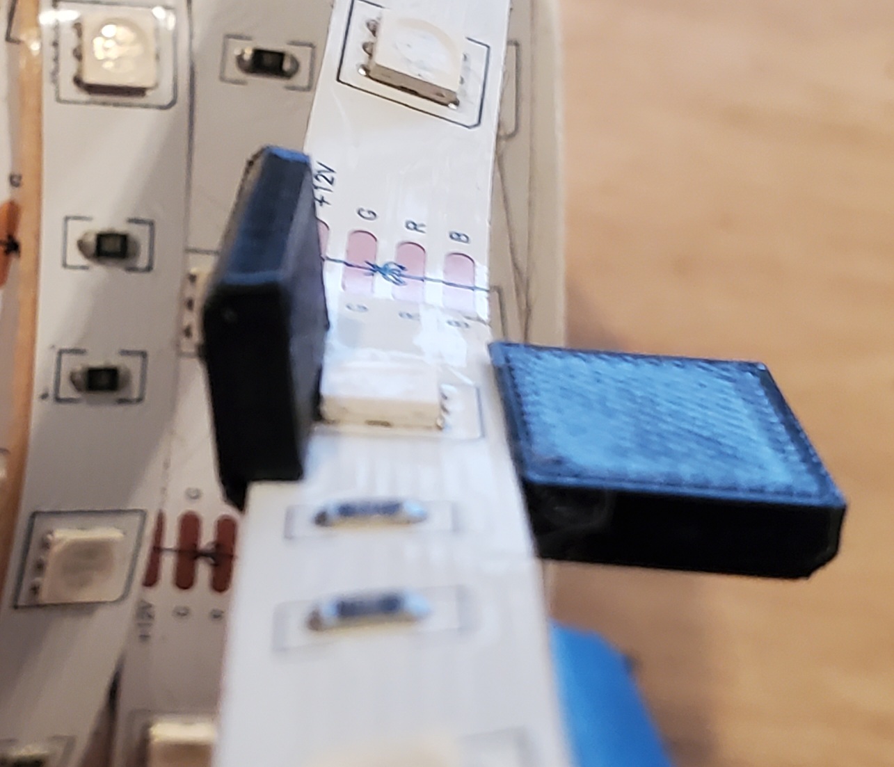
Attached is the two-part channel cut at 45 degrees at the junction and is 505mm in length. The angle cut was to prevent light from seeping through at the junction. I’ll work on the channel for the 2020 extrusion this evening. I may also give you an alternate channel that is designed for friction fit. I like the folding one better, but you may prefer the other, and it is simple to model.
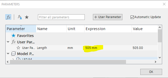
When I’m done, I’ll provide the Fusion 360 file with a user parameter for length so you can easily size them.
A tip about contact cement. Consider using masking tape to mask off where you don’t want the cement on your panel. Remove the tape while the cement is still wet. The two pieces are put together when the cement is dry. Once the two pieces touch, binding is immediate, so you will be unable to reposition the channel.
I understand this completely. I upgraded mine a few months ago and it was no where near as easy as it should have been. Still fighting issues with it (cant get an ESP01 to connect to save my life)
Thank you so much for doing all this!!! I will print this one today and see how it turns out. I think I will have to trim 20mm off the back side on each end for where the extrusion is but that should be simple and work well.
Thanks for the masking tape tip! I knew about waiting for it to dry and it being instant but never thought about the masking tape to make it easier/cleaner!
I will be headed back to work for 6 weeks either tonight or tomorrow night. Ill have to make some time and research how to get the SKR to control the LEDs and give the temperature lights and all. I think it will look good all lit up. Have to set it to red for normal lighting though for the logo LOL. The rest of my panels should be delivered today so hopefully I can find time to get them on the LR3 and cut out. I’m amazed how much of a difference the front and one side panel made in rigidity for it!!! without them it would flex all over the place anytime I touched it. These panels have to help a ton.
Ill have to make some time and research how to get the SKR to control the LEDs and give the temperature lights and all.
I’ve not used LEDs with Marlin, but I’ve bumped into the code and commands. Search for “RGB LED / LED Strip Control” in configuration.h to find the section for setting up Marlin for your specific LEDs. See M150 for the g-code to adjust the LEDs.
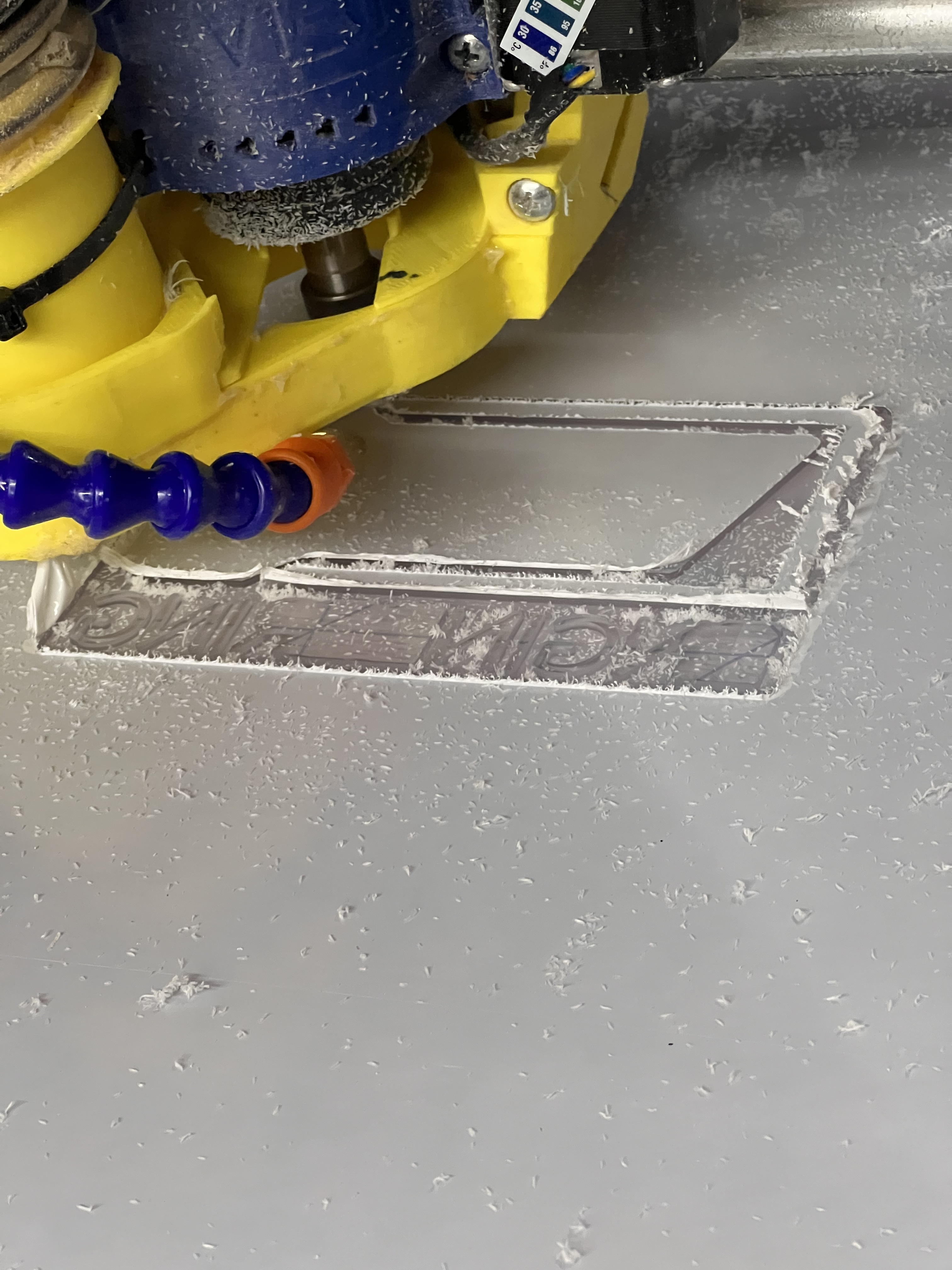
Posted already in my build thread but thought I would put it here as well. Currently cutting the back panel and decided the side opposite of the power supply looked like a good spot for another logo. Hopefully the lights from the bottom will make it show up good. Worse case I’ll light it from the top too. Thanks again @robertbu for all the help with this!!
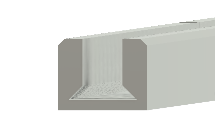
I modeled two additional channels. One is a 90 degree for use with the 2020 extrusions. The other is a non-folding, potentially friction fit version. I did not run any 3D print tests on the friction fit one.
Here is a sample print from the 2020 extrusion one.
I’ve attached the ZIP file. That file contains the Fusion 360 file for all three designs. You can set the length by adjusting the “Length” user parameter.
Then you just have to export the STL files. There are two bodies for each channel design so that a long channel can be printed on a smaller 3D printer build plate.
Feel free to post back about any changes you might want.