I have a few thoughts about your design, though since I’ve never built this kind of hold-down system, they are just my thoughts.
Given how small your working area is, you want to maximize the potential size of what you can mill. That means your holes should extend beyond the working area to allow the clams to hold things that span your working area. This also means that some of your holes will be hand drilled and not drilled by the CNC. That further complicates things, since there is room for error in hand-drilled holes.
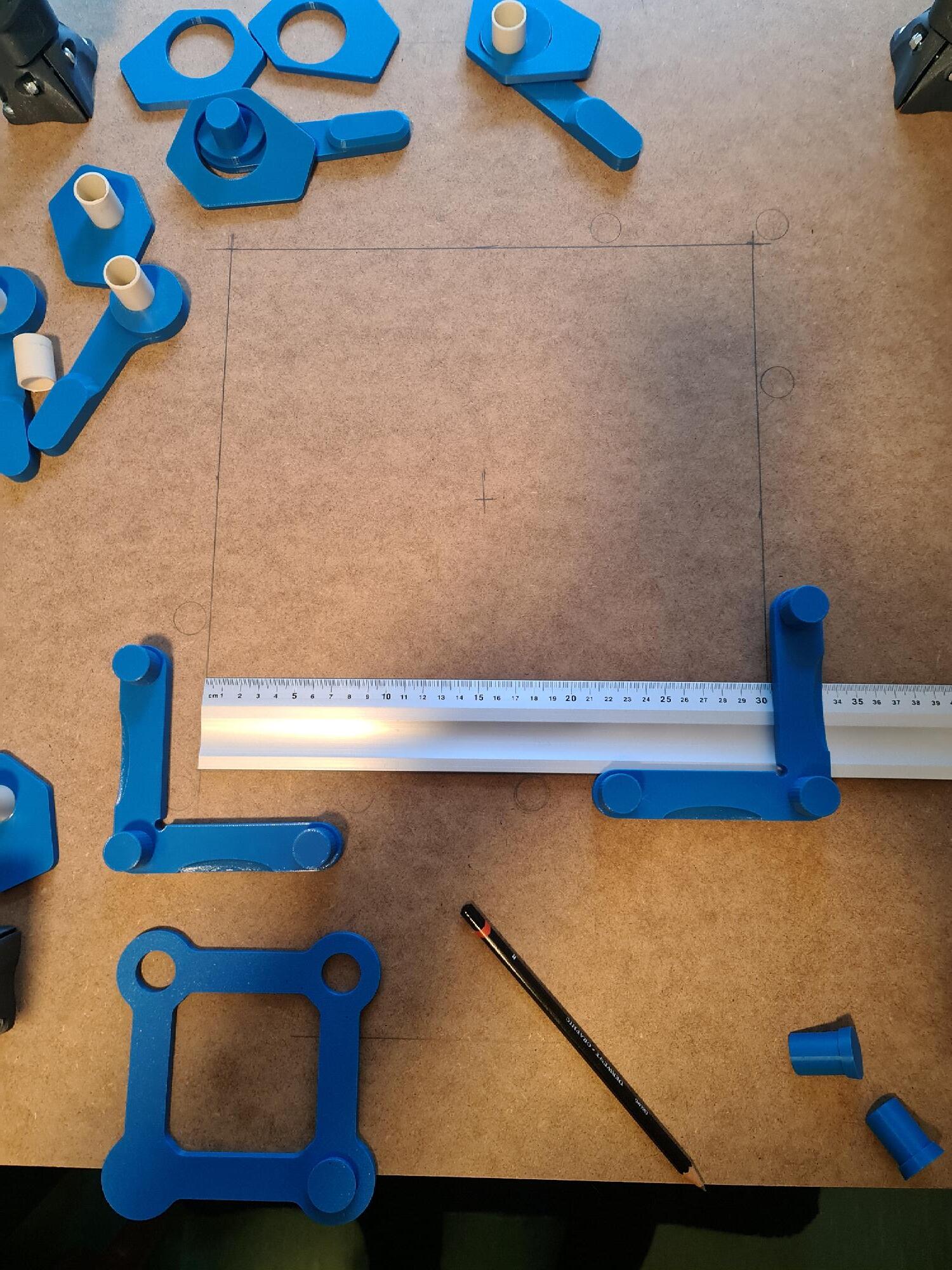
Make your corners out of two different rules (one horizontal and one vertical). Also make them out of wood, or some other mill-able material like acrylic. After you drill the holes and have them installed, use the CNC to dress the faces of these rules. This will ensure the rules are perfectly aligned with your CNC machine. I would make the rules removable using the same holes you drill for your clamps. Ther is no reason for two corners, but I cannot say it is a bad idea.
As for where to start the holes, I’d take a look at the cams you’ve designed and figure out where you’d place the holes so that cams could lock a 300 x 300 piece of stock in the working area. Note this is likely to change the spacing a bit, since you want your cams on both sides to barely enter the working area. Or you can place the cams well beyond the working area and use spacers. This is a bit more cumbersome, but allows more leeway in the hole placement.
I don’t know any software yet and I haven’t recieved the Makita router yet. I was thinking of pre drilling the holes with a drill and then mill them manually with the router.
I will be using legs that are 60mm in height and 81mm in z workspace height.
Here is an approach. Calculate how far out of the bounds of your working area the holes need to be so that the cam clamps will just lock a 300mm x 300mm piece of stock in the working area. This creates the placement of the row of holes at the top and bottom and the left and right. Since your working area is square, these should be the same. Next divide the distance between those row/columns to create a reasonable spacing.
For the “corners” create rules out of a mill-able material that use the holes in the pattern you created as to pin your rules to the spoil board. Have the “rough cut” rules extend slightly into the working area, then use the CNC to mill the edge of the material so that your rules are guaranteed to be aligned with your machine.
As a point of information, personally, I used threaded inserts at 65mm intervals. Given my hold-down strategies, 65mm was too far apart for me.
Historically, I’ve done a bunch of work where clamps would get in the way. Things like surfacing boards, or carving in prepared blanks. As a result, I designed several types of low-profile clamps. These clamps are less rigid than typical clamps, so I found spanning large distances between the inserts and the stock problematic. When I next redo my spoil board, I will go with 50mm spacing or smaller in support of these clamps.
Note when thinking of clamping strategies, consider that the router can lift stock. If your cam clamps are strong enough that would not be an issue, but it was an issue for my first designs of my low-profile clamps. Traditional CNC clamps hold down from the top as well as the sides.
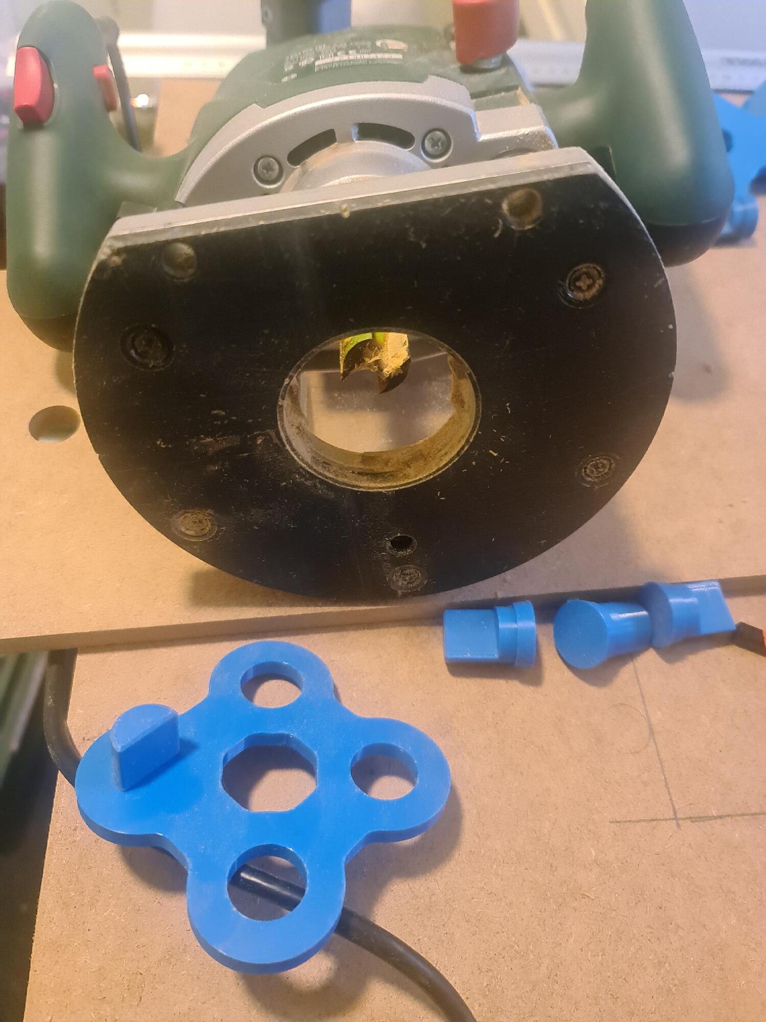
I am not quite sure how your template is meant to work - forgive me if I’m stating the obvious but you would normally use a router bush and size the template accordingly. It’s hard to tell if the router you have is setup for a standard guide bush or not, but if you don’t want to buy a bush it’s not hard to make one.
If you remix the router plate in your link to include a 30mm diameter guide bush and use a 10mm cutter in the router, the simple formula for calculating the offset is:
(Outside diameter of guide bush – diameter of cutter)/2.
For example, with a 30mm guide bush and a 10 mm cutter, the offset is (30-10)/2 = 10mm.
Therefore to make a 20mm diameter hole you will need a 40mm diameter hole in your template. With the advantage of 3d printing, you could of course make the guide bush as small as you want.
You could probably cut down the bush to 20mm diameter (10mm cutter, 1mm clearance all round and 4mm wall thickness of bushing. ) which would cut the diameter of the template down to 30mm.
If that’s not clear or you need a hand with the baseplate.guide, let me know.