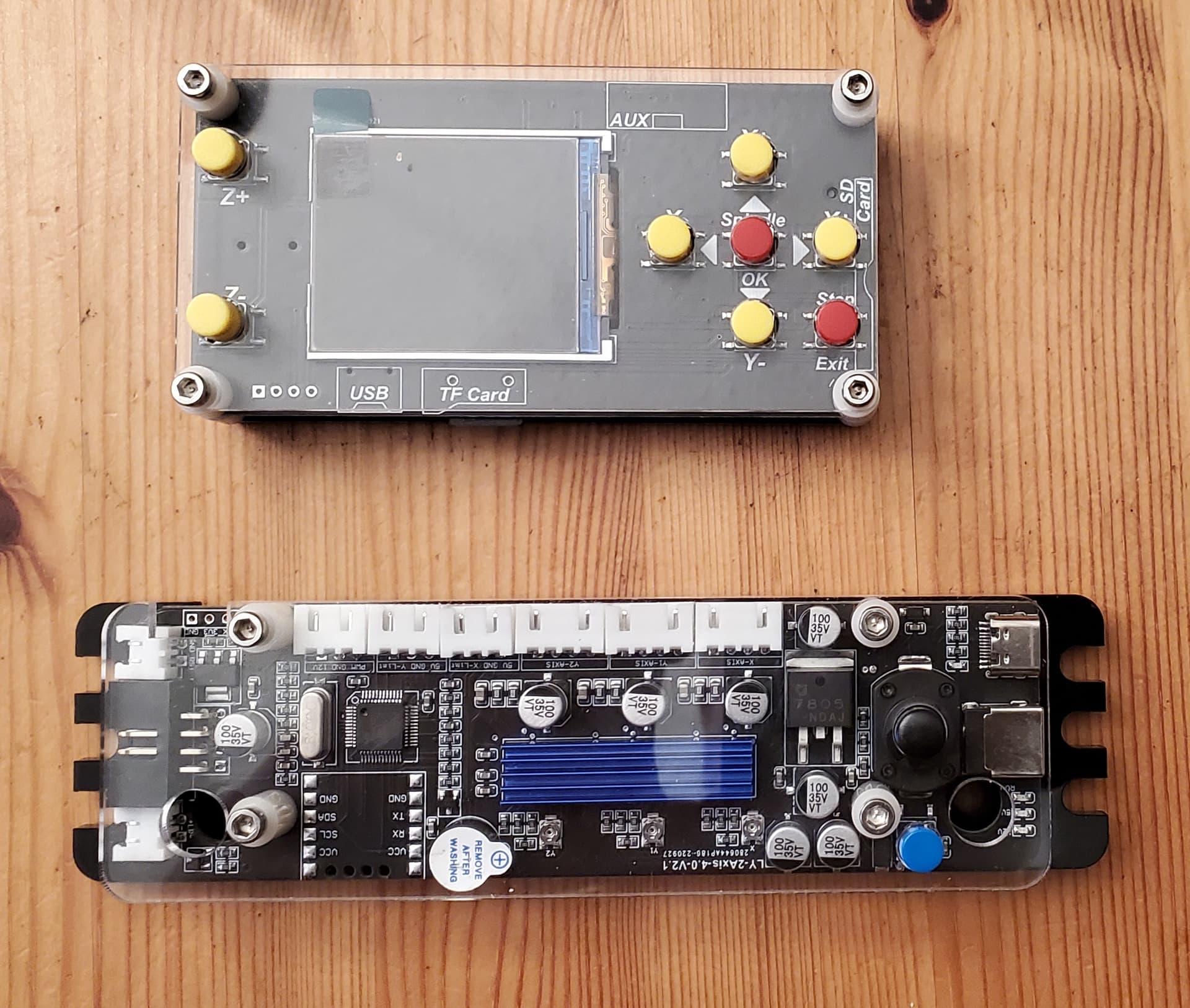
I looking for a way to identify the stepper driver on this GRBL control bord, or a way to set the current blindly without knowing the driver (like maybe putting an ammeter inline with one of the coils). There are pots on the board for setting the current, but I have no idea of the vref value.
I purchased this board and display on AliExpress. It is available on a number of store fronts on AliExpress and EBay and listed for sales in other sites. In the past, it has been sold on Amazon. Since it seemed so available, I thought once I got the board, identifying marks would lead me to some technical data. I cannot find anything other than the data at the store fronts. I guess I’m spoiled about how easy it is to find data for most Marlin boards.
It came with GRBL 1.1f installed, and everything seems to work. I can talk to it from LightBurn, and the display works. I just need to be able to set the current correctly.
I was thinking I might put an ammeter inline with one of the stepper motor coils, and then move the stepper around electronically looking for the maximum value. But if this works, will I be getting an RMS value? And if so, how do I relate the RMS value to the peak value provided with the stepper motor?
Alternatively, is there a forum that might provide some additional information about this board?
Note the Brand seems to be ANNOY TOOLS, I’ve also seen LUNYEE associated with this board. The only identifying text on the board is LY-2AXIS-4.0-v2.1.
Edit: I could pop off the heat sink from the drivers and try and read the top, but I’m trying to avoid doing that since everything is seated nicely, and I don’t have any heat conductive cement.
Interesting. They have to be a4498 or drv8825s. The a4498 are cheaper, so that would be my guess.
The a4498 can’t do 1/32nd microstepping, but they can both do 1/16th.
I don’t think the actual chip matters though. I think one of those surface mount resistors is the key. They have a numbering scheme. 101 is 10x10^1, or 100Ohm. But there are 4 per driver. I’m not sure which one is the sense resistor.
As for measuring amperage, you would need to catch it on a full step. Anywhere between two full steps is going to be some fraction of the max. I would guess it is on a full step when you start, but who knows? You can wire a resistor across each coil, and measure the voltage difference. Be careful not to short the negatives between the two coils. They are not going to have a common ground. Ideally, you would be looking at a scope of the voltage across each resistor and plotting it, while doing microstepping until one coil was totally flat. The current/voltage you will see on the other will be a PWM signal, switching between 12V and zero. The %on will be based on how fast the driver reaches the desired current. The current will be jumping above and below the set point. The average of the current is what we normally talk about as max. So if you are shooting for 900mA, it might be 2A for the on period and 0A for the off (the switching frequency is very high, in the 10s of kHz). But it will be on for 45% of the time. Your multimeter will average that out over seconds on the DC current setting.
What about going from the ultimate result though? If you plug in a motor to a driver you are familiar with, at 900mA, enable it for 20mins and then measure the temperature of the motor, and it is 45C, then you know that motor will be about 45C with a 900mA setting. Then do the same with the unknown driver. You would really want to avoid having to test too many settings (because each test takes forever). But adding 50% vref until the motor is over 45C, and then backing it down by 25%, etc would get you close pretty quickly.
My guess is that it acts just like a stock a4498 though, and I would start with that assumption.
If you learn anything interesting, let me know. I would love to have some good test equipment and a few days to inspect stepper motor driver behavior to verify some of my knowledge (and find hopes in it).
As always, your insights/information are very helpful. One big takeaway I had not considered is that, unless I can identify the sense resistors (and I don’t think I can), knowing which driver chip is used is meaningless. The idea of using temperature to determine current is also something I had not considered. The third implicit takeaway is that, if I am careful not to short the wires, putting ammeters inline with coils is a safe and reasonable thing to do. I won’t be able do the work until this weekend, but my plan is:
Test the temperature of my desired stepper at the desired current using a known driver. I have a RAMPS board with DRV8825 drivers for experiments.
Put a larger stepper motor (2A) on the GRBL board and put ammeters inline with both coils. Experiment to get a general idea of how the pot positions/voltage relate to current output.
Starting with a pot setting that I think is significantly below my desired current, gradually increase the voltage while testing the stepper temperature at 20-minute intervals until the desired temp is reached.
Read the voltage from the adjusted stepper and use it to set the other drivers (it is a 2-axis, 3 driver control board).
Is it actually necessary to put a motor on? Can you instead just put something like a 5 ohm 10W ceramic resistor? Given that the driver chip provides constant current, is it actually important that the load be a motor? A pair of ceramic resistors are cheap, and if you burn it out… so what? If I were to burn out an 84oz.in motor, I’d cry.
I’d only be risking one stepper, but the resistor is a nice idea. I don’t have them on hand, but my local electronics store sell 10W for around $1.00 ea. Is 10W enough or should I get 25W? My big concern has been damaging the control board, not the stepper motor. If I blow the driver, I blow the board.
10W should be good enough. If you are getting 2A into 5 ohms, that is 20W, but a 10W ceramic resistor will take that for a few minutes before it burns out, and at 1A it is only 5W. (P = I x I x R)
You can get the 25W ones if you like, or you can get 2 ohm 10W resistors instead, 2A into those is 8W dissipated. The actual resistance isn’t critical, since the driver will refulate current into any load.
I agree with the math on the big fat resistors. But you also already have two resistors built into a stepper motor. So I don’t think there is a problem using a motor you already have, instead of a resistor from the store.