Maybe the Never Slips From Weight 3DP?
I don’t think so. From the little testing I did with mine, I think the sharp edge of the metal plate digs into the belt enough to keep it from slipping. More testing could be done, though.
I just thought of an interesting belt idea. I’ll toss it in cad a bit later.
I’m torn on the bearing idea. Part of me likes horizontal on top. But I think the extruder causes the bearing to torque. The vertical bearing still has the same torque, but I wonder if more stress is on the upper balls.
Alright. This is an idea I had for the belt clamping mechanism. It’s partially based on something Aza mentioned.
The idea would be to loop the belt back on itself through a groove. An M3 bolt would be pushed through the hole left by the belt. Washers and a locknut would then be used to slightly squeeze the belt, locking everything in place. The gap in the metal plate that the belt slides through could be loose enough to not have to really fight the belt getting it in there because the bolt squeezing everything is the real holding mechanism.
The part, as designed, is in 5mm plate. Hole size could be adjusted. I was originally going to try this on my design for the current core, but didn’t take it all the way and ended up going the other route.
You’ll have to pretend that the 2 belts are connected through a loop. I didn’t want to try to figure out how to modify the McMaster-Carr part to make it do that.


1 Like
Thank you super clear now.
Okay, I see what you are saying for the two plates, they are needed, unless it is offset even more. With the bed floating and all the room we have (~4" on all sides). I think it would be nice to do just one plate in this case. That just means the bed is slightly more asymmetric, it does not waste any X rail room.
I have seen those belt clamps.
The distances are tiny so far it feels great.
That red part was just a minimal example. If can be attached to the bearings itself (without the plate, which kinda seems better) or with the plate and longer M3’s.
Yup, I should have read ahead. That last answer covers this. A one or two piece single printed part…oh I have an idea…is better than adding a metal plate for the sake of adding a metal plate.
I keep thinking about this. If a tool changer is the goal I think the rail core sideways design makes a ton of sense. Basically, just turn this printer 90 degrees and pick up tools from what used to be the front. In this case having everything sideways gives you the best of both worlds. SO I don’t think many design considerations would be needed. Tools need to be on the side of the rail that they are used and parked. so either we turn the whole thing backwards for everyone, or just have the people with tool changers turn it sideways. I don’t think rail orientation matters.
No adapter will always be the most direct. In this case printed sure seems to make the most sense.
For me this means model the belt holding as minimal as possible and any extruder mounting after, for easy customizing.
One plate is the best, the consideration here is screw lengths and some machining capability. Adding precise holes, countersinking. I think we just got to the whole decisions…I will add it at the end.
I think 2 plates is just added complexity. It moves the machining need of the one plate on to a supplier. So if I were selling full kits without an extruder, it would come with two plates. One machined to fit countersunk screws and hold a second larger blank plate that the user would need to drill holes into and trim down to fit their setup. So in my opinion we are still at the printed vs one plate.
fancy ziptie.
I would be using zipties… ![]()
I have no issue with these
If you were to use printed only this whole assembly would be one part. That would mean that red upright at the end of the rail is supporting it and is only 1.5mm from the end. I will say judging by the printed vs plate option for the LR3 XZ…no one will print it.
This part is only fighting gravity, from both ends, front to back is where the mass is multiplied by acceleration.
One side of the balls is going to be forced down, the other is going to be pulled up in either orientation. Ideally we could put the extruder on top of the bearing but the direct drive hot ends are just not long enough for this.
Okay,

This what I planned to do, but this way

From the top and in between the two parts. This method does not require it to be pulled into place so getting tension right is a non issue. Because it wastes none of the adjustability. With a two part design, the belts are locked in and can not come out.
My reasoning for them being in a printed part is milling that tight of a tolerance ~2.1mm or so slot in metal would not be easy or cheap.
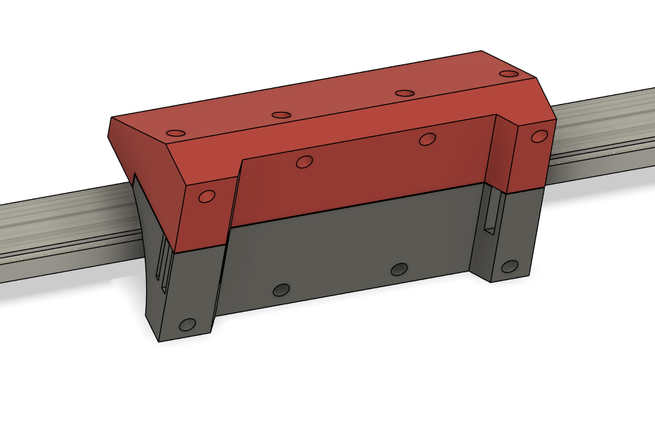
So here is a more complete thought on the core I had .

To get to the belts the top would need to come off, rare but might happen. The bottom half stays in place with the lower extruder screws. To the top comes off with two extruder screws and two bearing block screws.
With a generic block like this the holes can be moved or we can add a bunch of common hole locations to the one block.
The belts will come in and wrap a round a post like the previous reply, and one could go all the way through if we think that is easier?
For smaller hot end and extruder two piece systems the mass can be moved even further towards the center after the belts get terminated. This is probably nice to have to add some stepper cooling on the one piece extruders as well.
The bottom seems fairly well braced.

" So in my opinion we are still at the printed vs one plate."
Vertical means a single plate with holes that will need to be added (if you are machining the plates yourself that is no issue, If I offer plate sets you are hand drilling), offsetting the extruder is fine so all the screws can be accessed. It also means we lose the flat XY plate connection. Most likely a purchased belt clamp part.
Horizontal means, a printed part. That printed part would also need to be modified for any extruder that does not already have holes included. We get to keep the XY plate mount and the belts will get integrated in.
So it seems pretty close. To me the major factor is that plate, it sounds like you two are a bit more concerned with the extruder mount?
It is a close one. Everyone, feel free to weigh in. It is close, they both have advantages and disadvantages. Which do you prefer? If you are making one what seems like they way you want to mount your extruder and rail?
1 Like
The belt slots are not set in stone, they can currently still move in or out, or wider apart, maybe even closer. So don’t worry about the part that looks thin, I just eyeballed it.
1 Like
![]()
I’m not sure what you mean here.
I guess what I’m wondering, is whether the weight, likely 2-4 lbs of the rail/tool/etc. is going to be too much for this piece

Especially if it happens to get a little warm in that area. I guess I was expecting it would need some type of bracing or something to stop it from drooping over time as a printed part
Okay, well a few have used them, but I only sold 2 printed sets to hundreds of metal “upgrades”.
If you print in something other than PLa you will be fine it is only slightly smaller than what we currently have, but do you plan on actually printing this?? I am assuming no one is printing a part that can be self cut, or purchased from me.
I moved on to the assumption that we were going for as many milled parts as possible. This does not need to be metal. I am pretty sure I am making at least one out of UHDPE
Carbon fiber plates?
1 Like
As long as you cut them safely.
That’s why I asked. In the beginning, it seemed like the goal was that all parts that could be milled, also had to be able to have a 3D printable version.
If it was designed to be, sure.
Just trying to get a handle on the barrier of entry for building v4 vs v5
Still is. If you break one you can easily print a replacement if you had to.
If you are printing PLA on a farm in an unenclosed frame, printed parts out of PLA is fine. If you want to enclose it and heat your build chamber to 80C…you better use something more exotic.
my goal is to keep some plates on hand, but to also make it so they are very very easy for a beginner to mill. The first printers were “projects” for those that had a CNC and ddin’t know what to use it for…and I like that.
The few printed components could easily be made into a milled and a single 90 bend…
I used them for the struts on my LR3. Top notch work and really quick turn around.
Same
I LIKE this. I believe it would really beg for heat sets or if made from metal it would need to be tapped but that is super compact and versatile as far as extruder choices.
You could even put standoff holes to allow a back plate to be added to support the fan on the back side to even out weight.
You are never going to really even it out much. A hem era is 388g, a fan is 25. Moving a fan far away just decreases it available pressure / flow. Better just to get it as close as possible to try and avoid needing two.
Yes absolutely less is better though.
Once a bearing is loaded it is going to be stable, if you had it is at it’s balancing point it could introduce slop, so some load is good, and 400g@ 2 cm is far under a MGN12’s rated,~~ 180,000g@2cm
All this load is transferred to the rail connection point, that is really why I am keep stressing that one large integrated plate as the key factor here.
![]() It’s that low a ratio? Wow.
It’s that low a ratio? Wow.
I was actually pretty happy with the printed plates (Though I do like the steel plates too!) I guess it comes down to the aluminum plates are inexpensive enough… Or else it’s just the difference in cost for people buying part sets. People who print their own may have a much higher rate of using the plastic XZ… Could be the same effect with the printer parts.
I am much more likely to print parts than have them shipped, if I can.
1 Like
I like the idea of the plate. And seems like everything you are showing should be pretty easy to mill on any relatively tight LR3. I know my full sheet machine can do it. And for anyone concerned about milling their own you having the plates for sale in the shop covers that completely. Hell your LR3 plates are cheaper than I can go buy plate and make my own lol. Still curious to see if I can shave 1/4” down to 5mm with a nice surface finish lol
That was the exact bit I was planning to try. Forgot all
about that thread lol. Thanks!!! Now I just have to remember that in month when I get back
The belt hold down I drew up assumed the parts were being milled at send-cut-send. My assumption was that they should be able to cut a fairly thin slot in a 5mm plate for the belt to slide in.
I was trying to get away from 3d printed parts on the core with my thoughts.
Milling is expensive, only 2D laser cutting is cheap.
1 Like