Make up your mind!!! LOL
1 Like
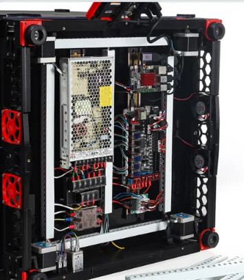
I hate bottom mount electronics. I like the clean look of the din rail mounted electronics in the Voron.
I almost certainly would make an extra side or back chamber to house my electronics, so I can access them, even if it is currently printing, as well as easily cool them
1 Like
Eating with family, so briefly… As you know my electronics sneak in under the Bed. Works, keeps back and sides clean, but not as accessible as side/back mounting builds. So…
Thoughts on CNC’d sheet metal or ACP based electronics enclosure that neatly folds into dimensions that fit inside the USPS box you normally ship. Ideally enclosure snuggly fits like a glove in your shipping box with the hardware packed within. Was thinking about this with quick connects for my build but never made happen.
1 Like
That picture is exactly what I was thinking, which is the bottom LOL
I have din rail coming for my E5+ conversion so I will get to see first hand how that goes. All of my printers except the V4 have bottom mounted electronics and I cant say that’s ever been a real issue
Exactly there is currently a ton of room 3+" on two sides and 4" on the third. I am far more concerned with minimizing that.
We have a ways to go before we get to the frame though.
1 Like
I’ll check back tomorrow.
1 Like
I think the original comment was meant to show that this is a great example of how to do the electronics, aside from the fact that it’s in the worst possible place for accessibility.
If this were a product, I’d say bottom mount is great. Given that this is DIY, I’d personally prefer to err on the side of accessibility. Then again, my solution to damn near everything is ‘get the scope’, so I’m probably not a reliable data point.
1 Like
Yes, in my mind, my wiring always looks like this. In reality, not so much
Oh I know. I was just messing with Mike
I don’t disagree. I was thinking do a bottom and mount the din rail facing up. Then have a false bottom to that which would be what is seen as the bottom of the printer from inside. Mostly I’m just thinking out loud
This is my current thinking as well. I have built tons of equipment with DIN rail mounting and various cable trays and terminal blocks/boards to tidy things up. It makes maintenance and upgrades so much easier in my opinion.
I think this is one area where you can really optimize further. Look at every mm of space inside the range of motion of the hot end, and minimize the distance from that volume out to the sides, top, and bottom of the machine. Once outside the frame, we can put electronics, touch screens, whatever to our hearts’ content.
One more thought about the flying bed- I’m not convinced that when you get up around 300mm x 300mm heated beds tht you aren’t already getting a subassembly with sufficient self rigidity that you don’t need the carrier- especially with flying motors and self-leveling. So, maybe the focus should be on identifying suitably rigid heated bed assemblies and just having some kind of heat-tolerant mount/carrier to attach the flying motors to that.
There is a inverted electronic mod for the Voron Trident which a lot of people do this with a liftable bottom. But have leadscrews, not a guillotine.
I’ve seen some extend the cables and put a drawer down there too for the 2.4.
2 Likes
Slotted ducting and extra length on cables like that photo is how the industrial world goes around. Just stuff it all in, cram the cap on and call it a day. I’ve shipped more than a few products using that approach.
Having a nice flat accessible space for like that on one side or the back would be the ideal from a maintainability/troubleshooting perspective, for sure. I don’t really know how that lines up with other constraints, of course.
Whoops, my mistake. ![]()
2 Likes
I’m not at all against having them on the back. I guess I am more looking to have them outside the envelope of the printer. Until now I have never cared about having an enclosed printer. But now I am thinking about it more so having the electronics outside of the printers heated area is more of a concern I guess. A wall on the back with din rail would be a great option. And while I’m thinking about it a better look at cable management all around would be nice. Not just a “its up to you” approach
@niget2002 did similar for his v4
2 Likes
Man I could have sworn I paid a lot more attention to the other V4 build threads but I sure seem to have missed a TON. When I get back to work and have more time on my hands I’m going to have to go back through them all and catch up!
1 Like
My reason for not doing that when it was as designed for the MP3DPv3 was that for a 300×300 XY, you need to extend a of the cables to reach. They only barely reach to the back or side. My MP3DPv3 has the electronics on the side, and the v4 has them on the back (though the v4 now has a standard size bed, it was initially supposed to be a 235mm square, so there is unused XY capacity. (The extra Y just means I can reach the whole bed with the BLTouch.)
I like the idea myself.
Late to the party here… Agree with most of the sentiments. The bed has dropped many times on this thing and nothing has fried, but I agree is doesn’t seem right and an electrical break or a stepper disconnect might be a benefit for the equipment.
I like the core xy and the bed moving isn’t a problem. 300x300 xy is ideal for me. I made the z axis 400 mm because I could, but have yet to use all of it. It is a long drop when the bed goes down, but with 2020 extrusion holding the plywood bed holder, it is reasonably light, but would be much heavier if it were supported by an aluminum plate. A counterweight system on the belts might be interesting, but anything complicated could be a liability for reliability.
With the goal of an eventual full enclosure, the electronics on my v4 are on the outside ( left) and some are din rail mounted. The vision was to put them under the bed, but after working around the moving bed and cleaning up under the bed area, and realizing that all the standard cable lengths would require extensions (partly because of the 400 mm z), I don’t want the electronics down below. An air filtration for abs printing and space heater could go down there, but for now it is dead space. I added 3 inches for that and 3 inches up top for a future lid that could allow the filament feed tube to move with the gantry.
Since I may not be able to keep up with this in real time, I would like to ask about the possibility of shrinking the dead space around the bed inside the frame. If it isn’t possible, then some false wall ideas would be helpful to better use the space for electronics and filament. Optionally enclosing and heating that inside area won’t be used for housing electronics or filament on my machine, so minimizing it would be ideal. Standard cable routing and bundling would be useful to aid with enclosing the top. The sides are pretty easy to cover and help greatly with racking and flex.
I will also mention that the front left motor mount tends to skew so the belt rides up on the pulley and sometimes lifts. The bottom ( motor side) of the mount has been pulled towards the front of the machine and the z motor attachment actually bound up on the mount. This may be user assembly error, but has happened. With the tension screw located above the belt pulley, a moment is created that tilts the motor shaft axis. The right motor with it’s top mount to the extrusion does not do this.
1 Like
I was just about to say why has nobody suggested counterweight?
For MPCNC and LR3 it adds weight to the moving part and it’s not really feasible but since the Z axis on MP3DP moves only vertically, it should be okay.
One concern I might have (which is also a possibility with the brake) is if the brake/counterweight is somehow unequal between the supports, it could fall slowly, but at a severe angle and maybe something else breaks in that case.
Three Z lead screws are boring but less can go wrong.
1 Like
Maybe a big extrusion ring around the outside of the printer? That would draw some attention.
I just want to add some salt to the stationary bed debate. If you’re worried about crashing the gantry, maybe flip the whole thing upside down. I have heard that there isn’t a good reason the filament won’t stick fine to PEI on the ceiling. When it cools, automatic part removal? If the gantry falls, it falls away from the bed and not into it.
My biggest concern with a moving corexy is that it feels like you’d need to duplicate the frame to make it rigid and consistently square. And it isn’t nearly as intuitive to adjust the square on a moving corexy.
3 Likes
I am only 24 hours late and already 139 posts behind… goodness. I think I caught up though.
My votes so far:
Bed Size = 300mm x 300mm x 300mm Standard Build
Cheaper to downsize than to upsize for those who prefer 200mm^3
Bed Style = Moving Bed with 4 Z Rails
I like the idea of 4 Z points. However, idk if this has been mentioned already, but aren’t we already using all of the stepper ports on the SKR Pro? Adding the 4th Z stepper would mean we need another Z driver, correct? Or are we proposing a different board?
Z Drive = Belted
Cheapest option. Also is the fastest option when homing. But yes, you do have the bed dropping issue. Personally, I don’t really care about the bed dropping, as it has never really happened for me. I have every print finish at Z Max and don’t experience power outages much at all. But I know there are some who deal with bed drops more than others so it is definitely a design criteria to explore.
I have more opinions, more desires, and more ideas to express, but I will reserve those until their topics come up. I will keep this post focused on these 3 topics.
6 Likes