There’s also the possibility that the commercially designed printers that use the V-wheel motion system are specifying all the parts appropriately. If they’re buying V-wheel specific extrusion or getting it made in big enough orders then it’s very likely that they control the critical dimension that would make the V-wheels work best. I know with the cheap 40x40 and 40x80 profile aluminium that I source locally there’s enough variance in dimension to have caused minor issues with parts I’ve printed as fittings for it, so I can’t imagine using a v-wheel with it would be a particularly fun task, despite the profile looking like it would work.
2 Likes
I like this!
This is what I was getting at. Each Z rail can pivot relative to the bed plate. Maybe the belt could be counted as mount points, but there are many reasons that is a really bad idea.
1 Like
That looks real good. Will look even better in aluminum
1 Like
I will print them all color coordinated one more time when it is all done before going to metal. I can’t wait to see it in metal…This feels pretty good. I have most of the bed mount worked out, and the belt holders as well.
3 Likes
Just realized sendcutsend have carbon fiber, acm and other materials… Are you milling parts, or got fiber laser, or using sendcutsend?
Tons of stuff in lots of sizes.
Milling myself, and sendcutsend, also oshcut, pcbway, jlcpcbfab.
2 Likes
That’s a good point. Plenty of designs for things like drones use stacked PCBs as structure. Cheap way to get accurate small parts in fiberglass with the added bonus that you get copper and marking essentially for free.
1 Like
Nice! Looked at latest Fusion render, the ACM sandwich parts are looking great ![]()
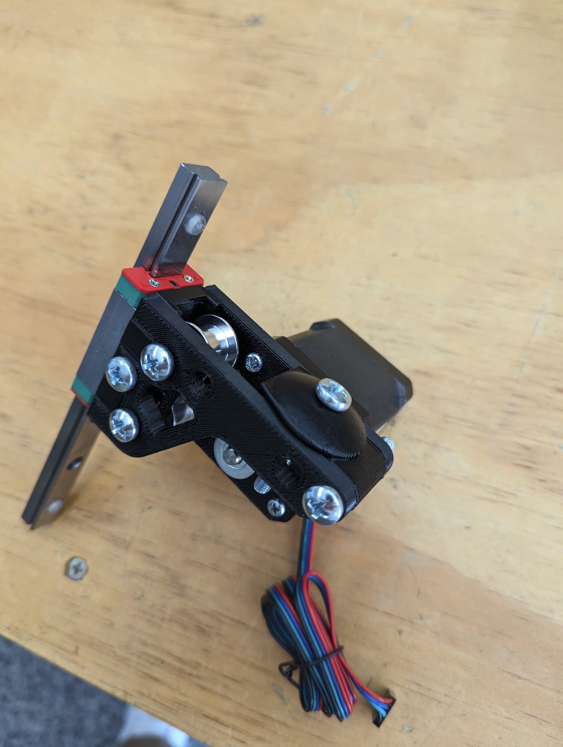
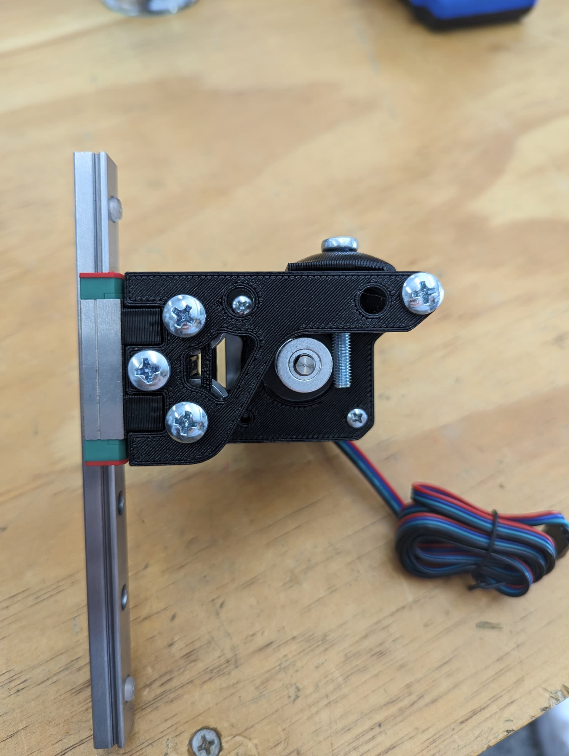
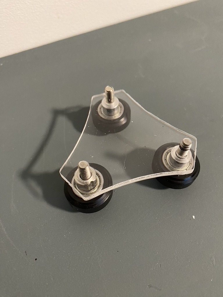
So here are some photos. I think for the cam/lock you will probably want to cut out of aluminum, the printed parts might soften in the enclosure and lose tension. I wanted to dry fit everything with mockup shapes first, and good thing that I did. The rails/extrusion didn’t align centered as I expected.
Here are the photos. I will put this on the printer and see how it works tomorrow!
2 Likes
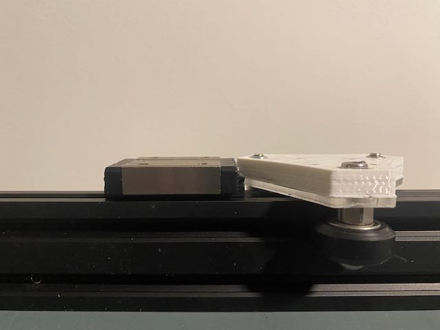
I used an extruded part for the spacer…with nut races…or whatever they are called.
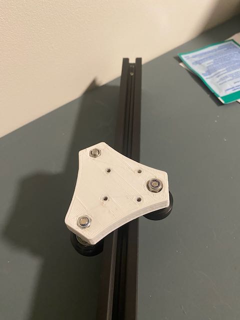
You can see from the top down that the alignment with the bearing block should be good.
Also, it fits the same height profile.
4 Likes
Did you heat set threaded inserts? Also, where did you get the cam lock? I searched that on amazon and I get ikea furniture parts… oh I just got 13 wheels delivered today. my next machine will have wheels on it and I’d really like to try the carriage… just don’t have the cam offset for the bolt
2 Likes
They are parts bin parts but if you search Amazon for: Eccentric Spacer, 5mm Bore, Column Isolation for V-Groove Wheel Aluminium Extrusion 3D Printer, you should find them.
No heat setting required. When I create a part in Tinkercad with nut races I use a 6 sided cone, with the bottom radius the correct nut size 4mm (8mm nut) and the top radius a little bigger 4.5mm. I find the nuts set themselves as they ease into the races.
I learned when I was building the Primo, to always hand-pre-thread the nylock parts.
3 Likes
That is awesome. That saves me a ton of work. Anyone that wants wheels, can now do wheels!!
3 Likes
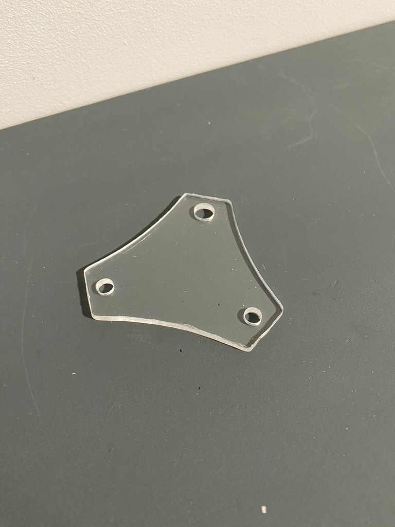
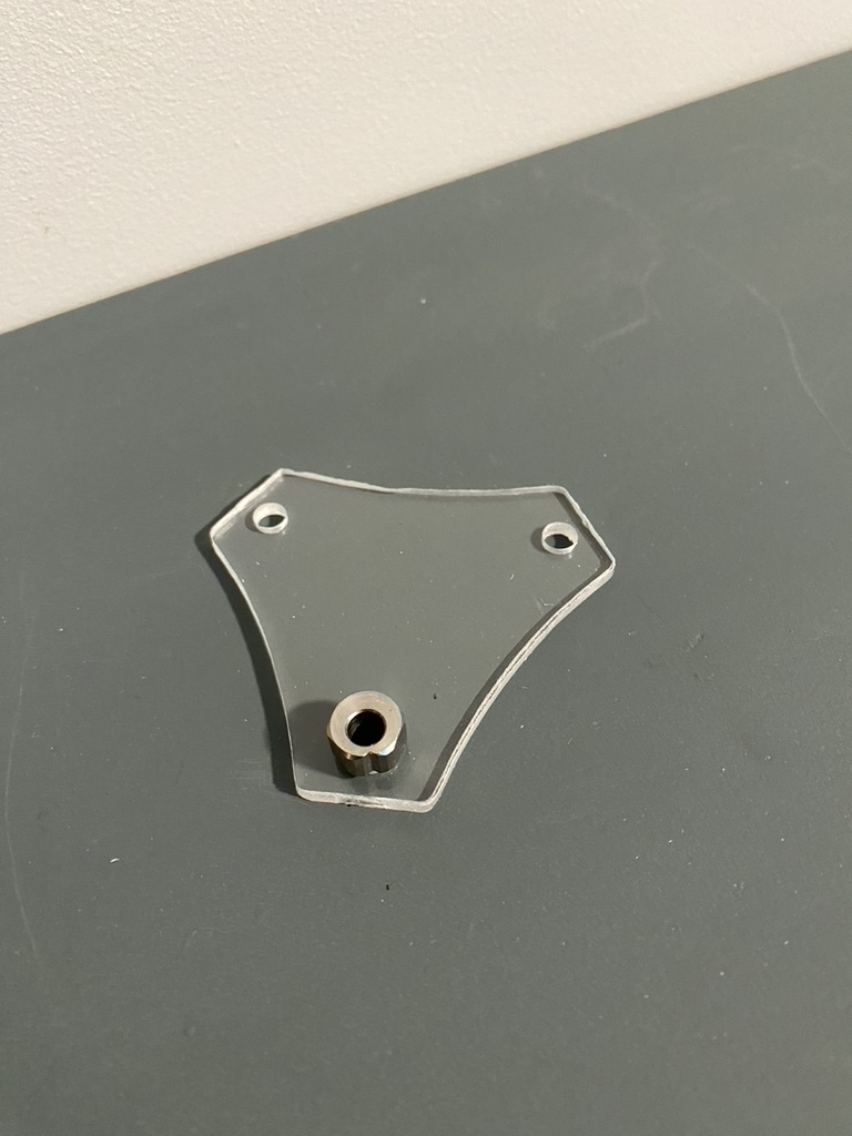
Those triangle roller parts are really interesting. I hope this works!
But…
Not quite yet , it doesn’t. You’re not accounting for the linear rail that the bearing block rides on.
Good news is you just need to go thicker on the upper part.
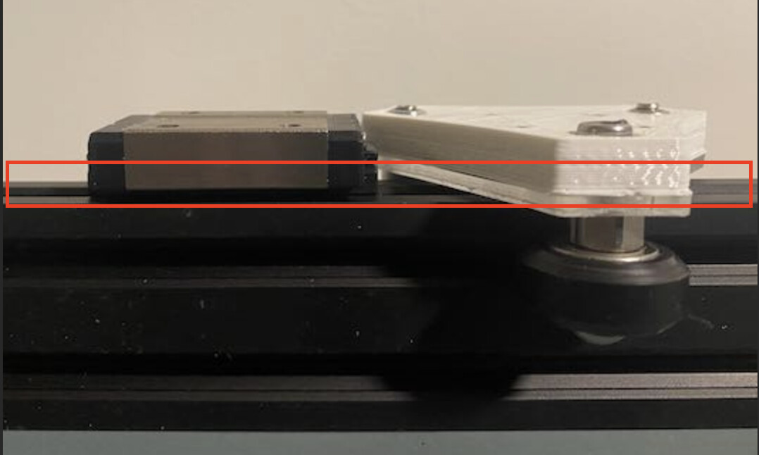
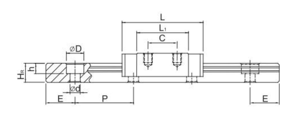
You need to be 3mm higher at the top, that is the height from the linear rail to the bottom of the block.
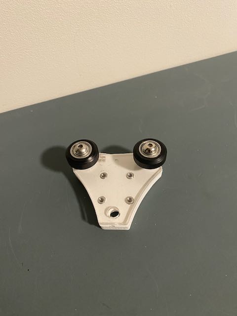
Did you mock your X carriage up on that V wheel block to make sure there isn’t interference with the triangle shaped parts protruding +Y/-Y outside of the MGN block footprint? That would interfere with the extruder mount and its assembly.
Seems like the examples shown in your posts up above would all need to be redesigned to clear the roller triangle. Or maybe this is for consideration only for Y axis and Z axis use?
Mounting the X rail would need different consideration at the end where it attaches to the Y carriages.
Given the design, id swap everything but the x for wheels and put the linear rail in for x. Buy only one rail instead of 6…
I think I’d keep the rails for Y. Much as I figured the wheels and V slot was good enough for the laser, I won’t likely be hitting the same speeds withnthe laser as I darn well hope to with the printer in X/Y.
Pretty happy with the laser, I cut one more Flite Test model with it, then another foamie of a Stinson 108-3. (My mother owned one, and I’m making a model of it, for R/C flight.) No R/C parts for it yet, but I have a general design for the airframe based on old photos of the plane, and some internet sourced material.
Sweet. I might well borrow that idea to replace MGN12 rails for other noncritical motion systems.
It is hard to see, but there is a small plastic bearing retention holder on the bottom of that block. I think my parts account for H =13mm
For those of you wondering about weight you would be increasing the moving parts for the Y-AXIS by about 50%…
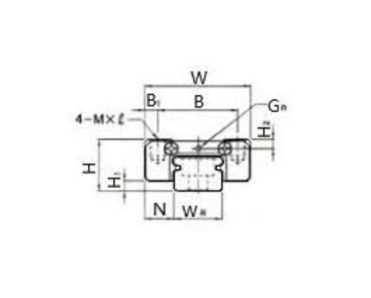
MGN12H = 50g
This contraption = 85g.
My response to the comments about mounting the parts where clearance may be required. This updated model should work with most MGN12H | MGN12C applications. I am going to try it with a bed slinger I have linear rods on at the moment.
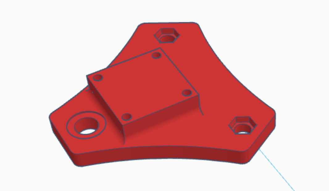
Model is updated again at mp3dp-printed-z-axis-substitution
I can’t wait to try carving this! Going to order some .5" acrylic!
4 Likes
This would only be for the Z axes. I would not recommend swapping the X or Y.
2 Likes
I agree, but there were some comments about clearance for the Y Axis / carriage. I think the new part should work, although it is 50% heavier, and it will need to roll on-top of the extrusion making it possibly a challenge to enclose the printer.