Seems like a lot of added weight that’s not really needed. But maybe I’m just not following you correctly.
2 Likes
You thinking (for vertical linear rail) to just 3D print Y truck, don’t bother milling?
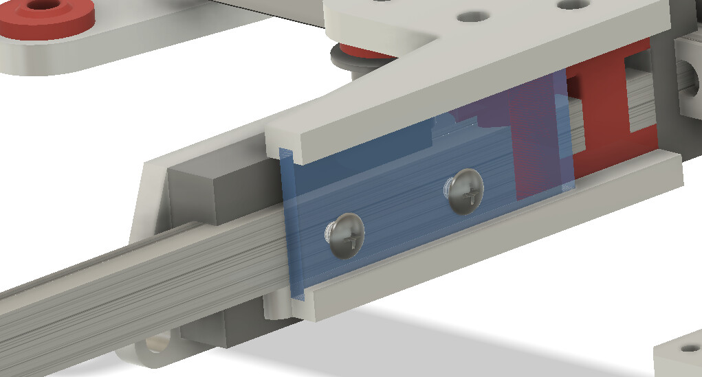
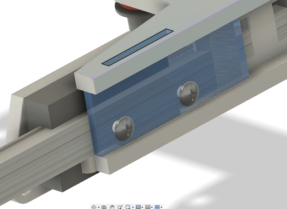
If milling, sketched one way for mounting X rail to truck…
Or… If recess channels are more $$$ than full depth laser cuts, then maybe full depth slots, something like…
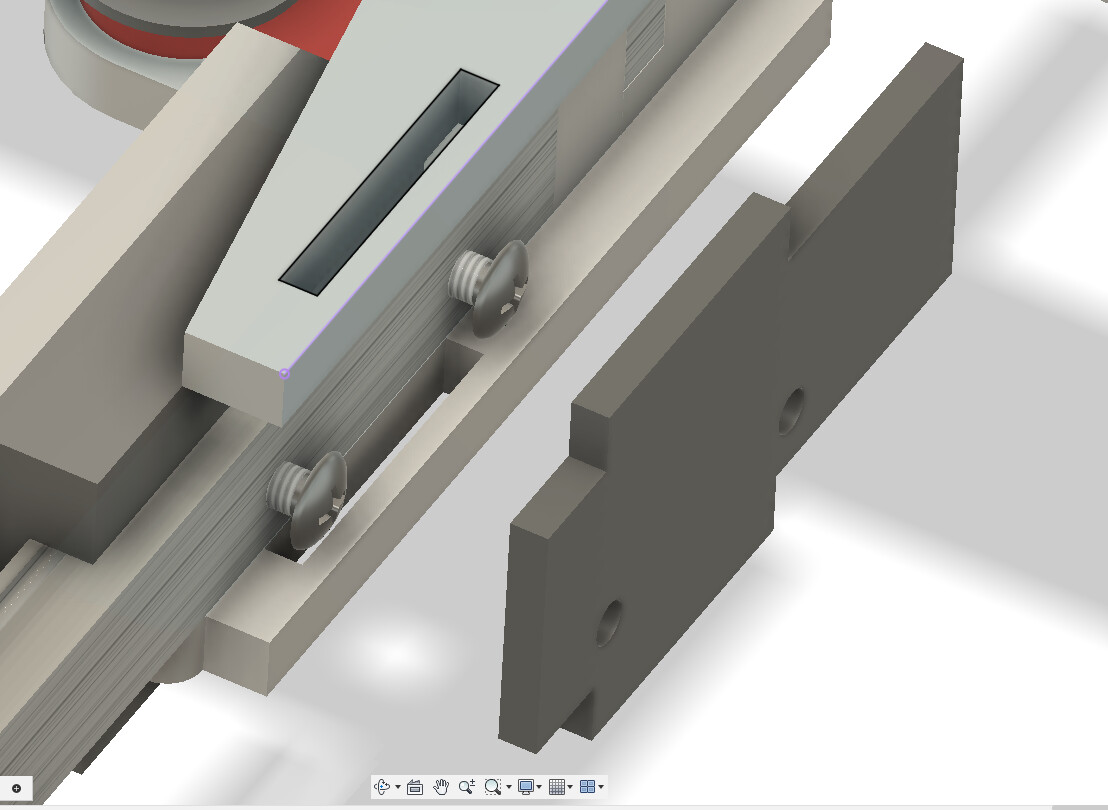
Maker still epoxy/glues/welds during assembly, so there’s no movement/slop (?) in the vertical plate connecting top-bottom plates.
If router milling instead of laser, then, dogbone/rounded corners needed for slot cutouts.
I’m thinking horizontal rail with bearing on top. Just how Ryan is setting it up. Simple flat milled plate that any one of us could do on our CNC machines, or can get made at SNS for cheap. Turing the rail and epoxy and all that is something I defiantly don’t want to mess with. That to me is extremely overcomplicating things.
I mean absolutely no disrespect to your idea and I hope I didn’t come across that way.
1 Like
Doesn’t have to be tapped by hand. Could have pressed in PEM nuts or use helicoils.
Now we have everyone thinking!!!
1 Like
My wife isn’t going to take the time to read and disrespect my silly ideas, so I’m counting on folks here too ![]()
2 Likes
I like the three piece sandwich. a lot of work, but it could work. Move back the the middle again.
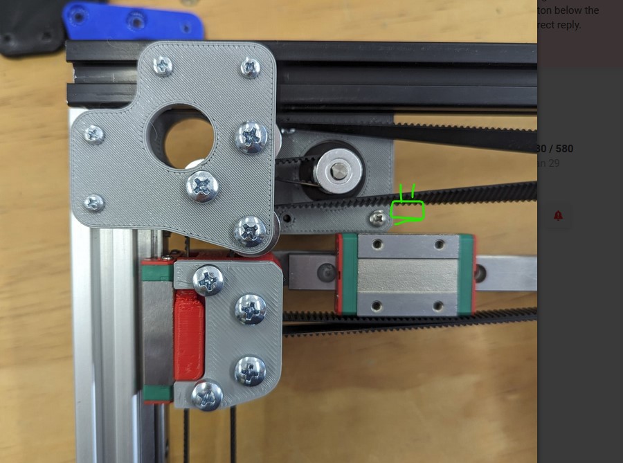
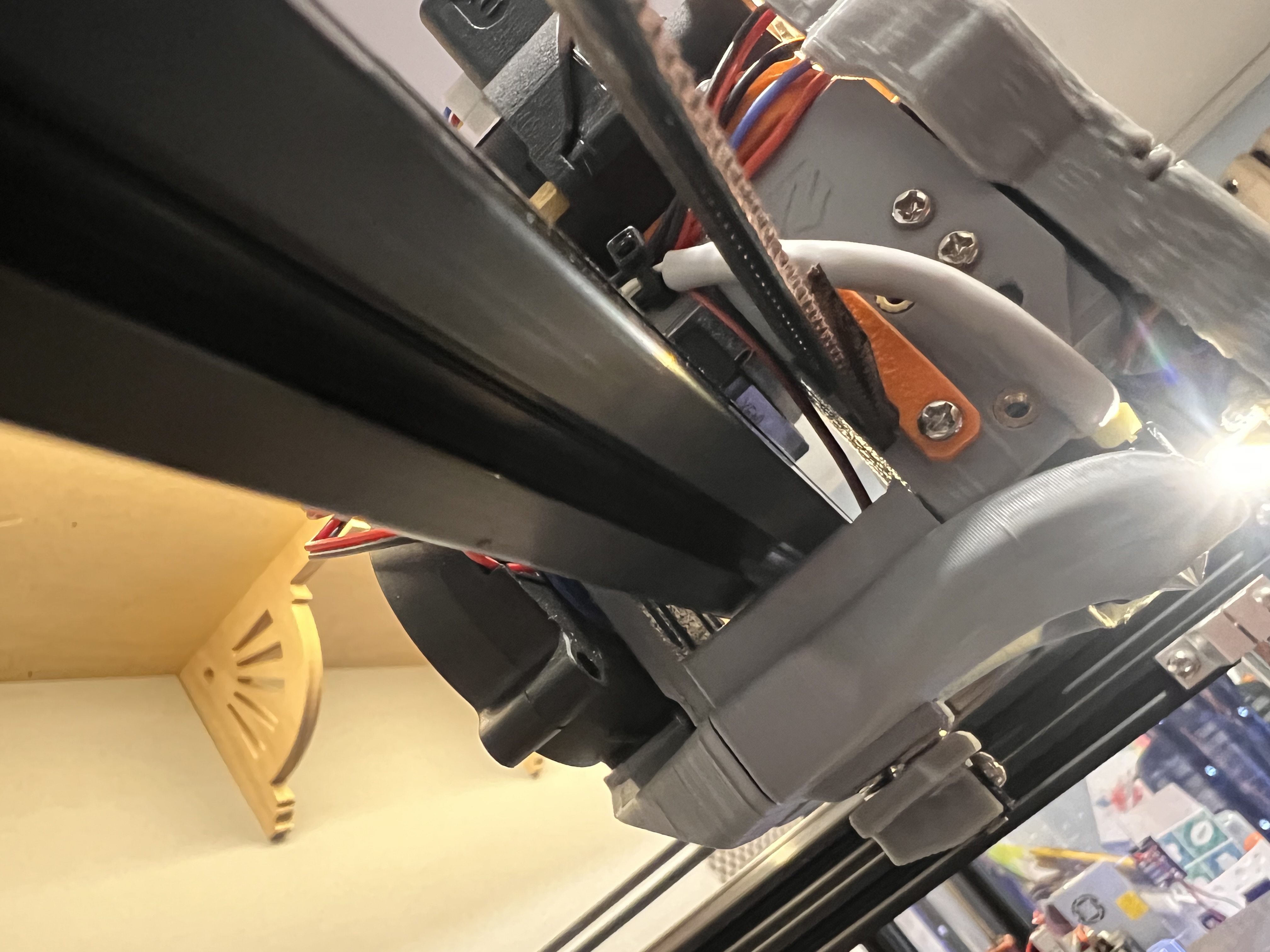
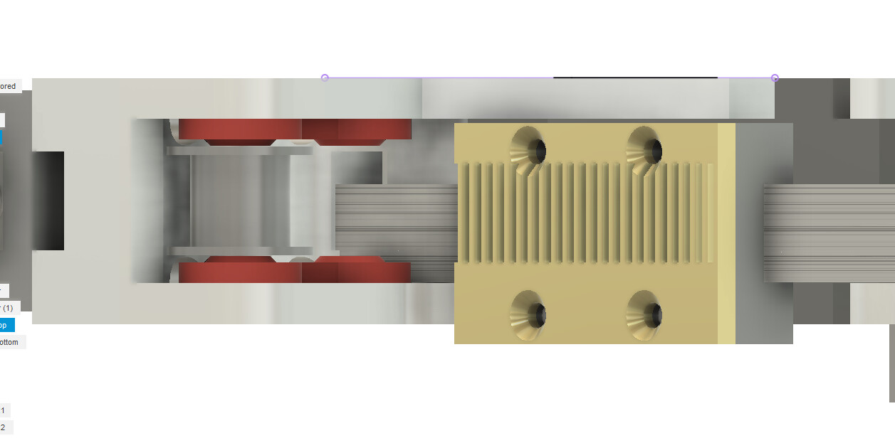
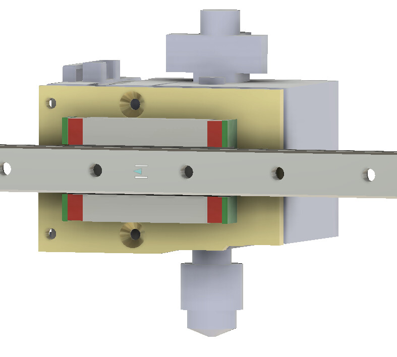
Did you notice where the belts are in this picture?
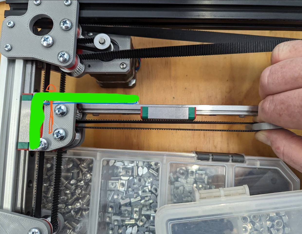
They either need to cross right down the center (like the trucks are) or way above or below the screws.
You can mount the rail in front of the belts or where I show it is about as far back as it can go. So the extruder would need to be in front of the second belt by a bit.
Putting the side mount sandwich and the way that extruder will mount, how different do you think it will be than horizontal? I think either way the extruder is always going to be sitting right in front of that front belt (we can bend it back a hair). It is looking like the extruder will be in the exact same place either way.
So how would that vertical mount look knowing that the belts are at the middle of the bearing block, or have a really good side mount.
I honestly think the mount is going to look nearly the same either way. Screws facing up or screws behind the extruder.
Maybe think of it this way, vertical there is more stuff in the way, horizontal you have more access. 13mm vs 27mm, 8mm vs 12mm.
Following that logic the mounting holes seem better vertical if you can get to them if they are behind the bearing block it is all bad.
Looks like we need some extruder mounting patterns to see where they land.
Let me see if I can get some actual mounting hole locations and draw in a vertical rail as well to see where things land. That might solve this for us.
Before I forget…
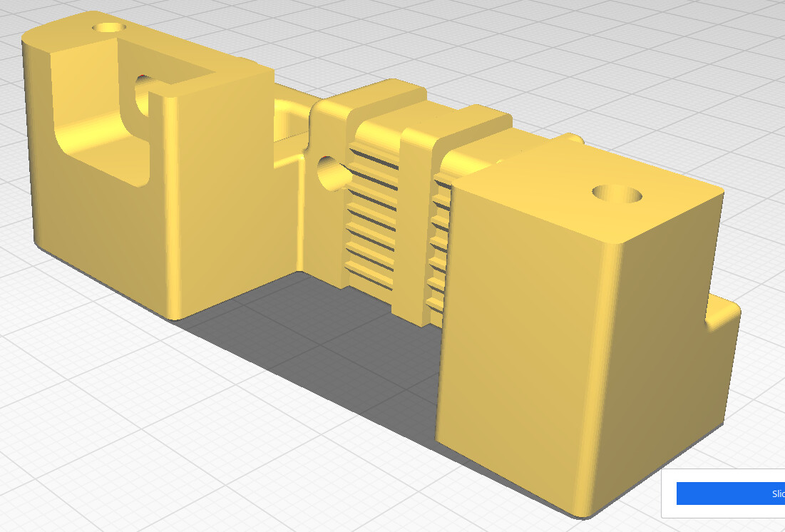
Hot-end wiring for power and thermostat need a path up to CAN Bus (or umbilical). Easy to channel in 3D printed Core. With milled/laser cut plates routing may require hole, or, (milled) recess channel in the plate, if the backside is a busy/restricted.
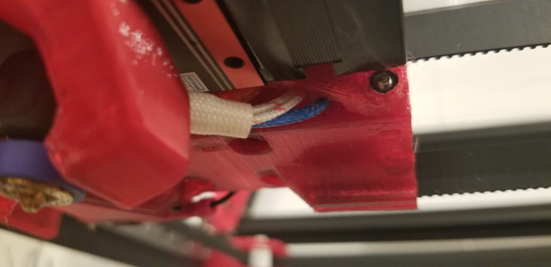
Pic above shows Mike’s H2 adaptor mount which includes a channel for hotend wiring.
Yeah, thinking…
If optimizing for performance..
  - Then...
    - Belts close as possible to center of rail block
If optimizing for easier install, and future belt tension adjustments...
  - And expecting busy wiring upper rear (?)
  - And providing no plan rear Fan duct part cooling, (?)
  - Then...
    - Belt below the rail block screws
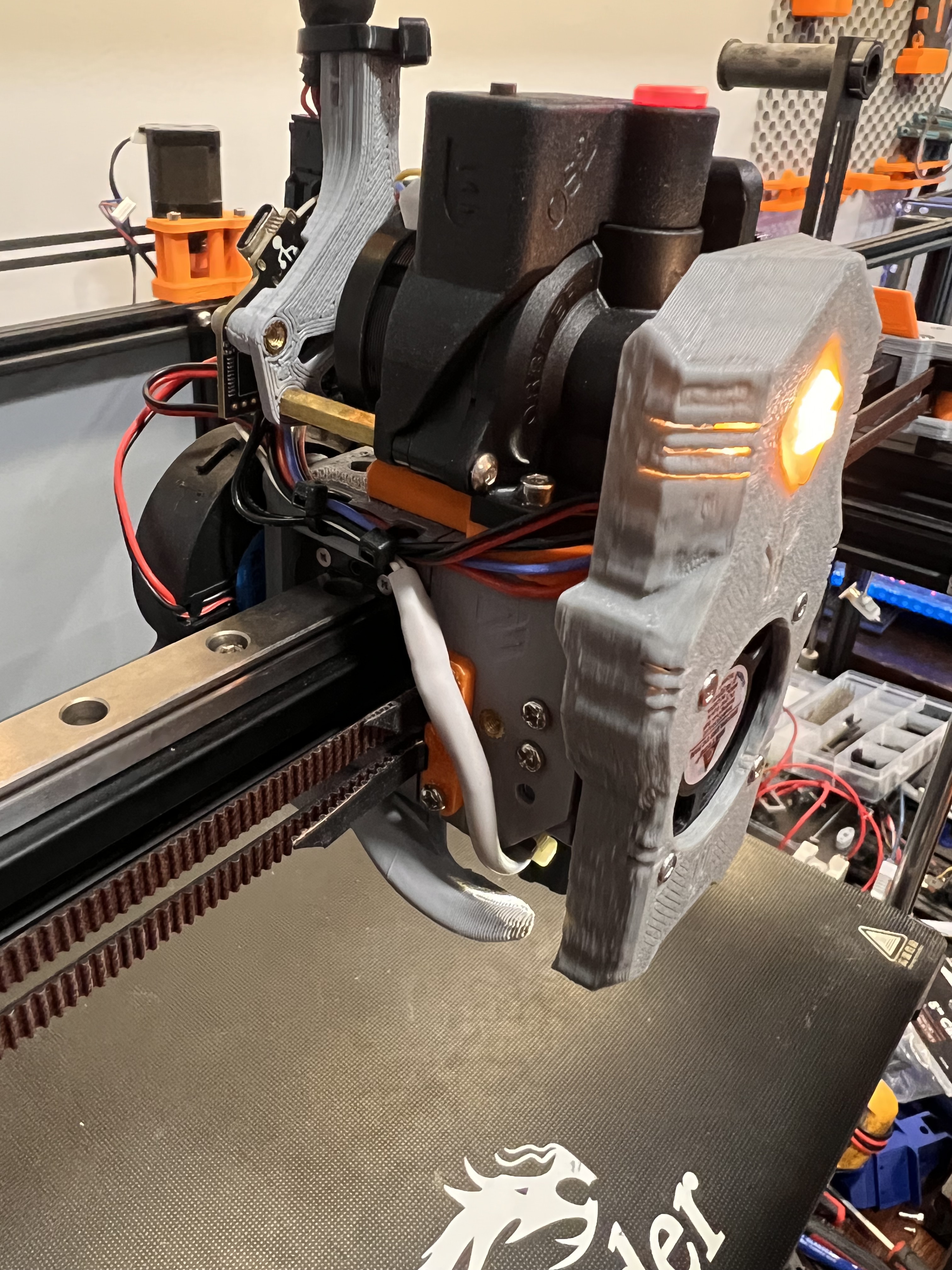
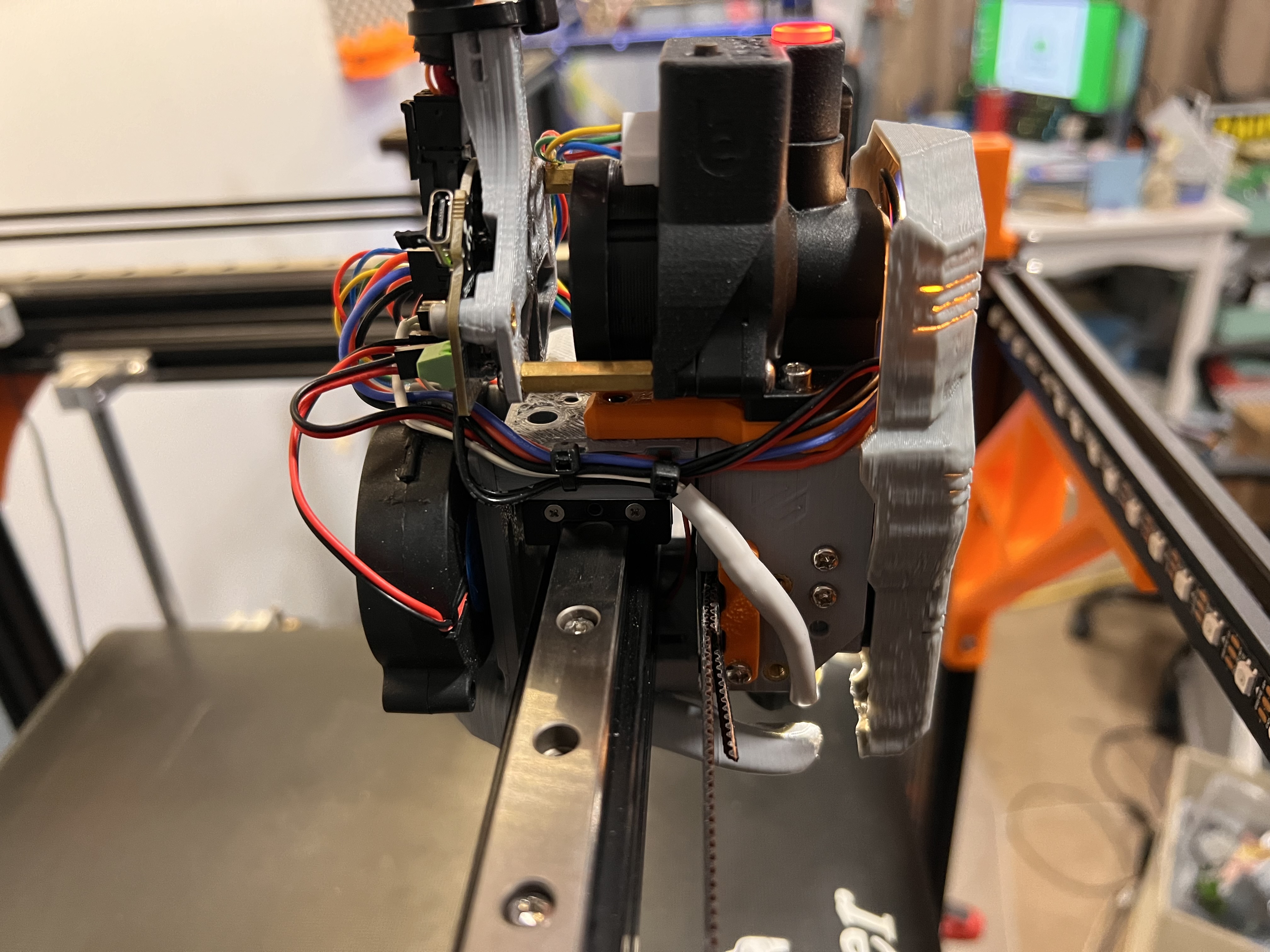
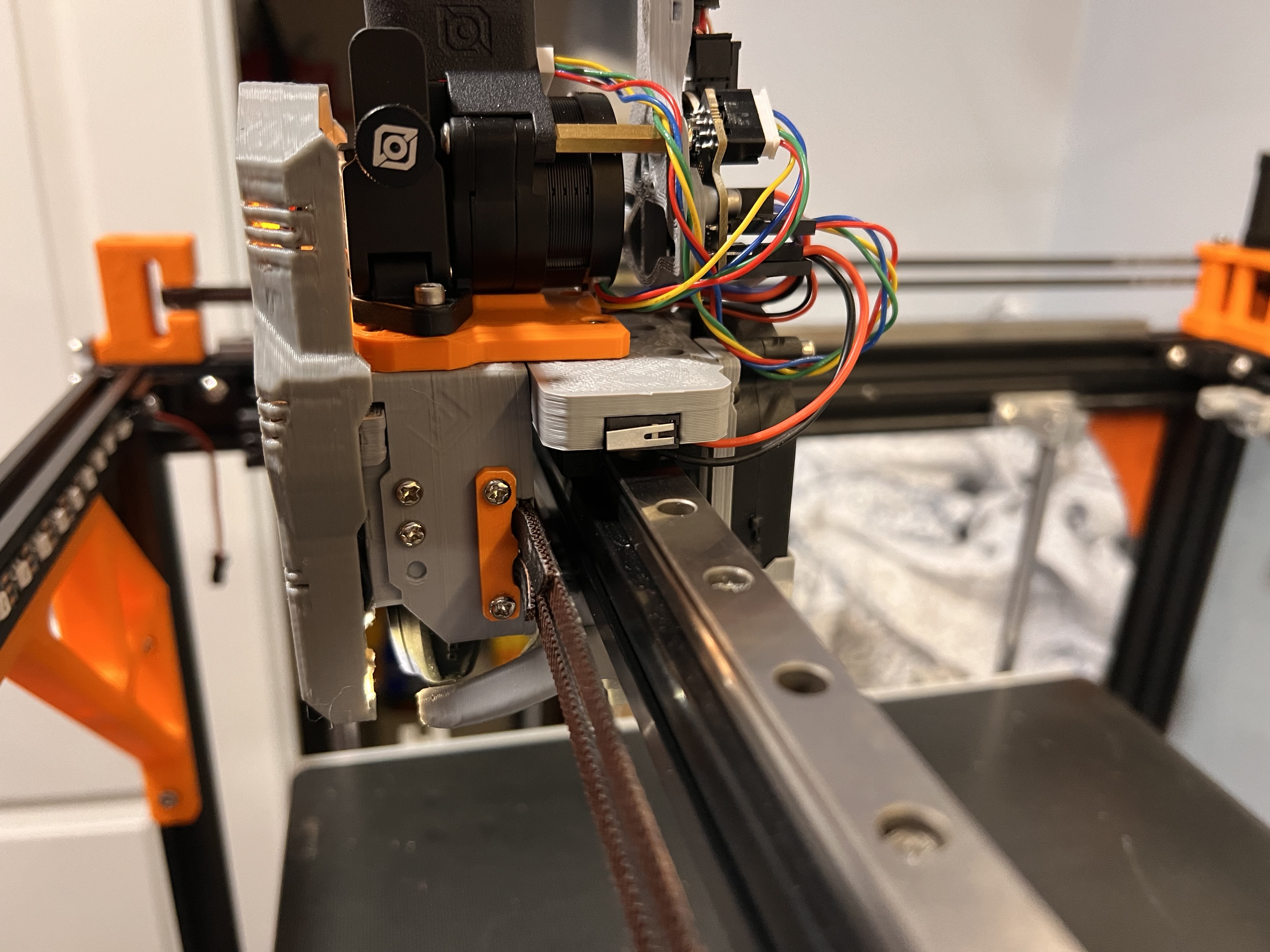
Here is how my setup is on the E5+. I get its different but just some things to look at. Belts could be easily modified to come in together and without the extrusion the whole thing has plenty of room to move around/adjust. Tons of different mounting options already designed for it. Tons of different cooling options already designed for it. This is an orbiter v2 and a Rapido HF. Separate units with a short piece of PTFE in between going though a printed part that could easily be an aluminum plate instead. I know we aren’t quite to this topic yet but this is to give some ideas on different setups other than just the hemera style one piece extruder/hotned. The current V4 is locked to that style without major cad work to make it all mount. Maybe not major to some of you but it is to me.

@vicious1 if I’m too early for this my apologies just nuke it.
2 Likes
Dead center of the core so far there is room, right about where I show that green drawn in switch.
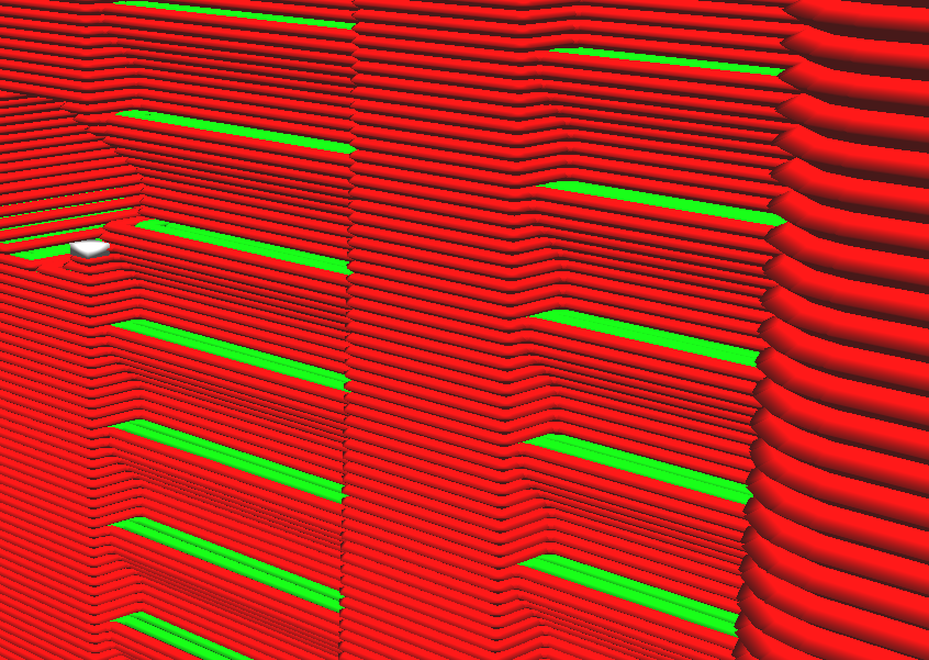
Checked how accurate laser cut plates are…
- 6061 Aluminum Laser Cutting | SendCutSend
- Cut tolerance +/- .005″ (0.127mm)
- Min hole size .016″ (0.4064mm)
- Min bridge size .014" (0.3556mm)
- Min hole to edge .020″ (0.508mm)
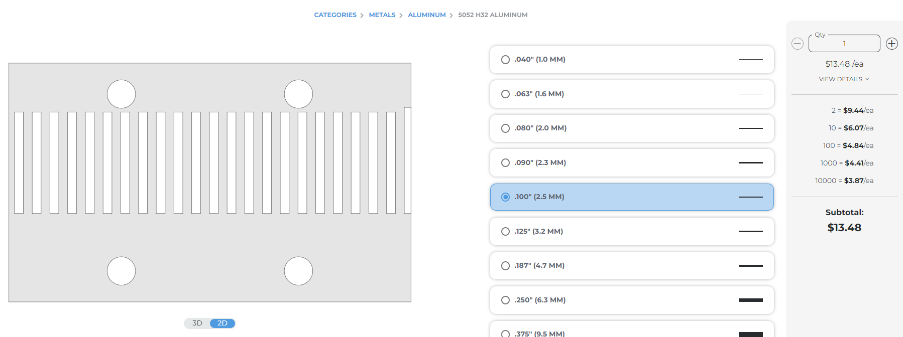
Checked price difference for making grill plates…
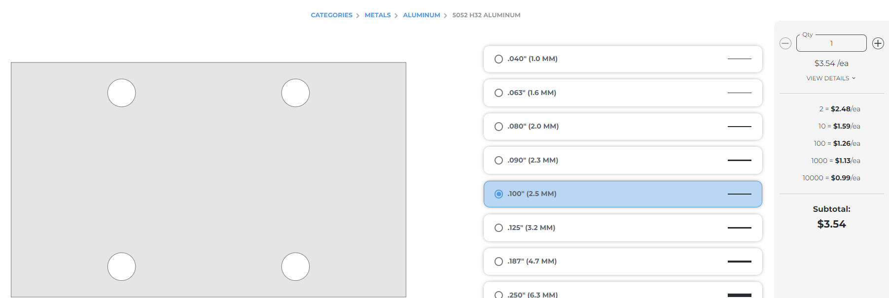
Another reminder of how relatively cheap, and easy 3D printing parts is.
To avoid 2nd plate from rocking (or Extruder if just using one plate), then, would you need printed parts, or be able to recess channels in the metal plate (adding to plate labor/cost…).
Shame the belt teeth are not facing towards the perforated single plate.
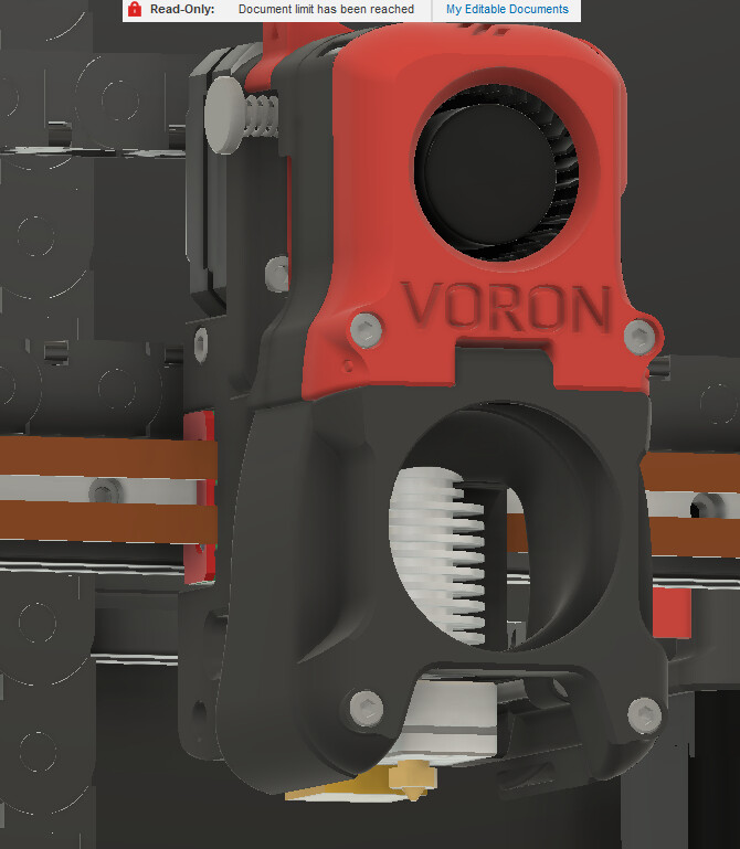
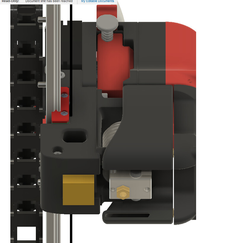
fwiw, looked at Stealthburner used on Voron. Stack belts right against the rail block, nice. But then…
Induction sensor is located closer to linear rail than hotend ![]()
Briefly looked at where Hemera mount holes, and rail block holes are relative to each other. Single plate looks possible if plate holes have countersunk bolts…
But, during assembly, would probably need to insert countersunk bolts for the extruder (but not fasten), before mounting plate to rail block.
Left-right center of mass will likely be off because of how close the inner most countersunk bolts will be. Don’t know if that matters much.
Even with all those holes, there’s room for belts too across the rail block, but would need to mill a channel. Ok for one off personal use, but $$$ to outsource? So, guessing 3D printed one plate with holes and recesses/channels for belts would be good enough for most people.
If belts along the X rail end up with teeth facing each other, then maybe there’s an opportunity for them to grip one another. e.g. Belts enter from the sides, then routed to be smushed/meshed together, pinned in place against the rail block, when the one plate is fastened to the rail block.
To be clear… Personally don’t have a strong preference for vertical v’s horizontal linear rail. Look forward to seeing what you decide, and come up with.
1 Like
I would argue the exact opposite. With a larger thermal mass, you will get much more consistent bed temps esp over long prints. Enclosed variants would also benefit from more passive heating in the chamber because of that larger thermal mass.
Flying gantry is really cool, and it certainly makes for a lighter Z movement. My concern with it has always been inducing more vibrations into the gantry as there are more non rigid parts. That being said, if you start REALLY pushing accelerations, having the gantry and there for the moving mass down low on the machine adds a ton of stability without the need for a ton of frame.
Motion systems are a thing that seems to be always debated. I was watching a video from rep rap fest somewhere and the team that was designing this particular printer had found that with carbon filaments being more widely used, it was causing linear rails to fail earlier because of the carbon dust (micro dust maybe) getting into the bearings and such. They were getting much more longevity over their tests from wheels. Which bring my brain to something the exoslide system.
The exoslide works on smaller wheels than say the stock Vgrove but because they reference several surfaces, they are far more accurate than the old ender wheels for example. Its an idea that could be easily adapted to whatever needs you can throw at it. They are basically 3d printable and mimic the same concept as the MPCNC and LR motion systems.
I had done some very minor looking into linear rods with something like a derlin bushing for being the smoothest possible motion system I could think of back then. But sourcing the linear rods that are actually true and straight became pricey fast. That was a couple years ago. Fast forward to now and all the commercially available big dogs are doing exactly that. It has be looking at my old Anycubic mega that has rods on all 3 axis thinking I need to salvage parts and use those to try out my ideas.
3 Likes
the use of an exsisting toolhead platform such as the stealth burner, eva, mantis, etc certainly does lend itself to easy configurations changes. However they all started with on set up and got modded by users to hold damn near everyting under the sun.
as an example, look at the different options available to this toolhead I am installing on my E5s1.
https://www.printables.com/model/539219-evantis-5015s-toolhead
2 Likes
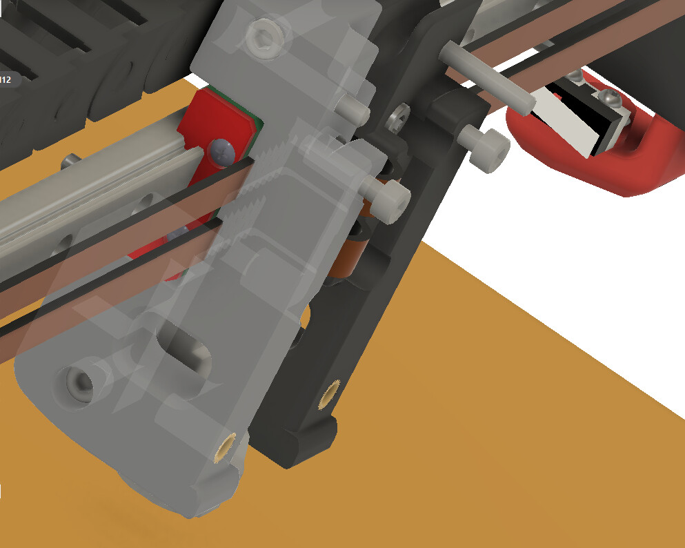
For vertical bearing related to belt location. What about moving the rail forward so the belts ran behind the rail opposite the bearing block. Belts on one side, bearing and extruder on the other.
2 Likes
this is interesting, but I would rather see the motor shaft supported by a bearing of some sort opposite the motor. This motor stand for example mount the motor shaft down, through the toothed pulley into the bearing. Makes for a much stronger shaft with alot less play. Also holds up to the force of the belts in motion better esp in a heated (either passive or active) chamber.
1 Like
this is ancient technology from back in my AI3M days, but look at the belt mounting on this toolhead. Its for a bed slinger so things arent 100% the same, but the idea is still pretty good imo. Belt swap can be done with the entire toolhead in place and it gives room for fine tuning tension.
1 Like
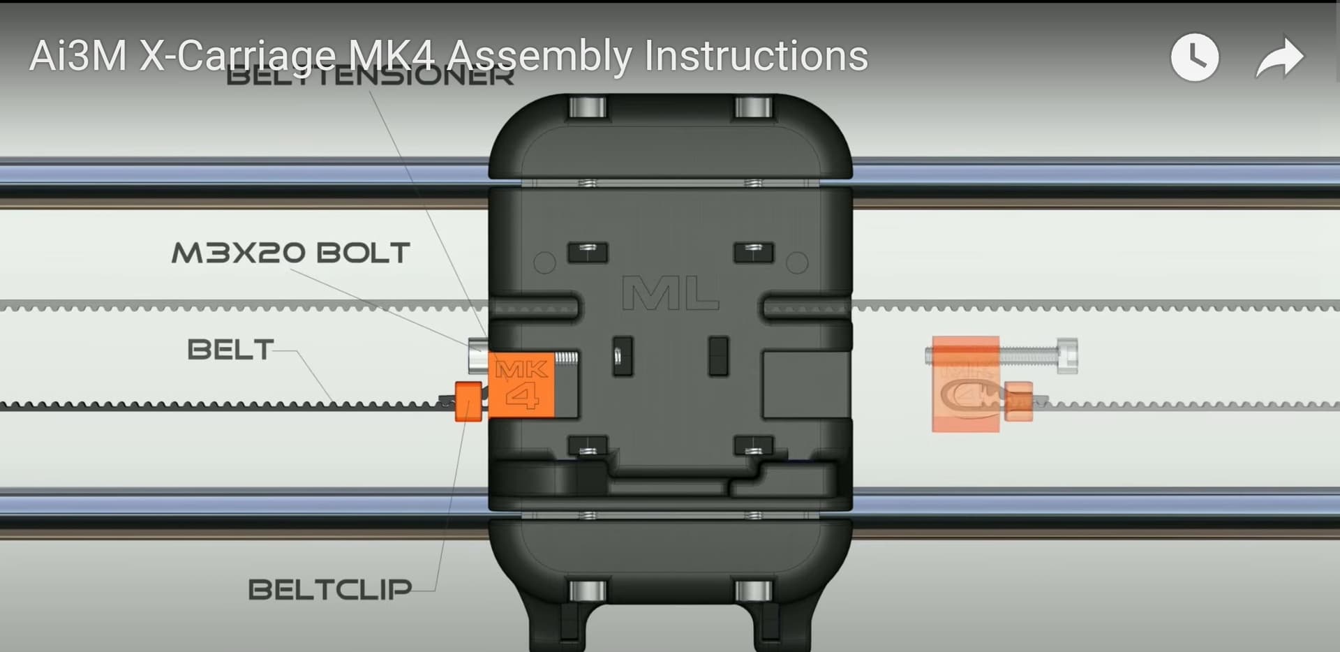
Neat!
Screenshot from neat Solidworks Composer based assembly video https://youtu.be/LadxXGYkU20?si=chBJK_c4Sm_lBA75
1 Like
call me an idiot but why only one bolt in vertical? There is a bolt hole where that bumper is…
double edged sword.
Pulling on one section of belt allows for finer adjustment, but means it needs more travel to accomplish the same as pulling on a pulley for example where the belt is tightened twice.
I dont fully understand your question? Yes we could use as many holes and screws as we want. On that design it only needed one. Esp with the captive nut design because you had steel on steel for not going anywhere grip with a decent amount of plastic in the middle. I was just showing the method as an idea not a specific “do exactly this” type of thing.
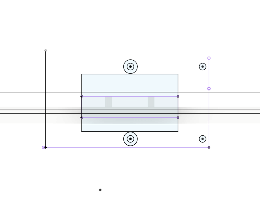
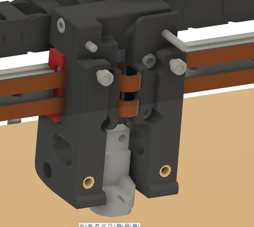
They fit fine either way. With the vertical rail you are absolutely locked into vertical position. The purple shows the horizontal block there is room to move it up and down.
That point is the nozzle tip. The closer that is to the rail the more efficently we use the Z axis space (that is where the bed would start).
- note the hemera is the Worst case scenario, not necessarily the recommended. If the hemera fits everything else should as well.
WHAT?!! 3 days of going back and forth and you don’t care? Boy…you are grounded.
The exoslide is amazing I have messed with it in person many times, I do not feel like an extrusion would work very well as a X rail though, not under today’s expected accels.
If it bolts onto a flat wall it should be fine.
It would work but to go behind you need to go behind the bearing, rail, and rail nuts. Also fine, but that expands the width of the Y truck to be able to spread the idlers.
The steppers are very able to handle the correct belt tension, but we did discuss this earlier, you can simply add one to the top plate. (I have some steppers that have been in use 24/7 for years on end with no signs of failing)
I do like supporting the shaft, in this case it is just not going to be the default, but there is sufficient room to easily add one.
Metal plates are what you would use if you are heating your chamber if you are heating to 80C.
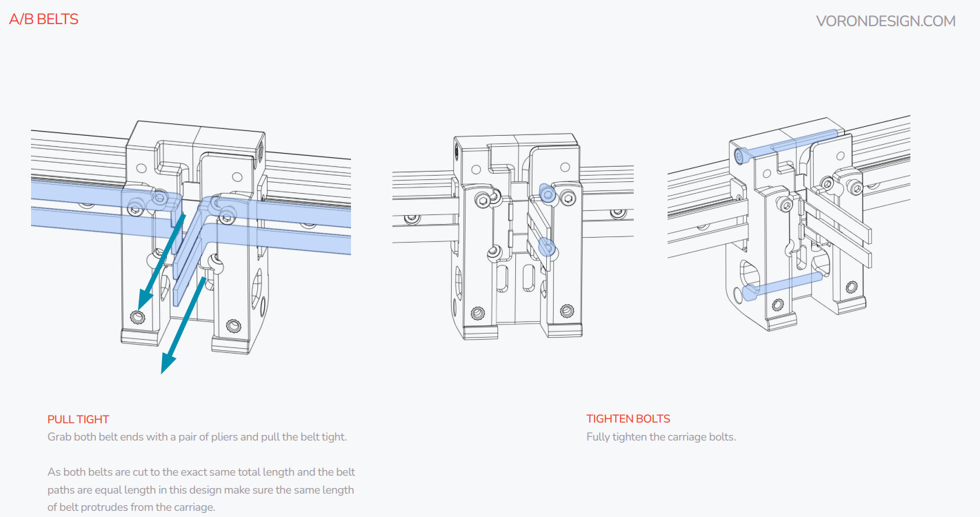
Looks like what we are aiming for, just a looped belt, just no need for extra hardware. we are moving the hardware off the moving head to adjust tension at the front idlers
2 Likes