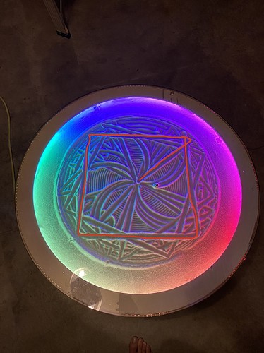
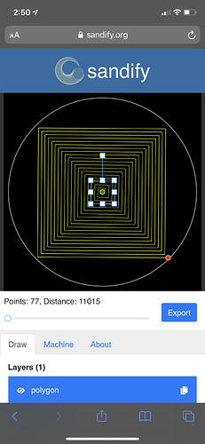
So something is way off and I have no idea how. I’m wondering if I’m not converting the number of steps between the 1/4 software micro steps or something.
Actually, I can see exactly how that would be a square… If the rotational steps/radian were defined as steps/degree. Well maybe not that ratio, but if the firmware thinks that it’s moving about 90 degrees, and it’s actually moving about, say 9, this is very much what I would expect the output to look like.
Radians to degrees would have a ratio of about 57:1, which seems more extreme than this.
This looks more like a ratio of about 8:1, which could be microstepping. It could also be gearing depending on the mechanism. This is however much as I would expect the output. It puts the ball straight out from the centre, then as it rotates, it brings it in towards the centre again, and back out to the original radius. What is different is that the expected rotation is 90 degrees, and it is only a fraction of that. The remaining lines of the square repeat the same pattern.
I agree. Try changing the microstepping from 4 to 32. I bet you have all the jumpers under the driver and that is making the drv8825s use 1/32 microstepping.
Any suggestions on what I need to look at changing? Basically the rotational speed needs to be increased relative to the linear steps? Or is it not even close to that simple?
Sorry for all the questions, I am a software developer by day, so that part I understand but I am lost when it comes to the math…
Awesome, I will try that right now!!
Ifr there was a hardware modification I needed to make to my stepper HAT I definately didnt do that as I thought I could control that through software like this:
M_Rot.set_microstep('software','1/4step')
Wow I think that did the trick. New picture:
Sorry for how messy the sand is, the square is hard to see but I just wanted to try it quick.
So now my question is should I switch everything to 1/32 vs 1/4? What is the pros vs cons?
Also thank you both so much for the help and quick responses!
1/32 microstepping allows finer resolution, so I’d probably leave the hardware that way, and make the software match.
The one reason why 1/4 might be better is if the python script can’t step fast enough. It is fine to run it for a while and get the feel for it. Then, if you change it to 1/4, you will know the difference. My guess is that if it is a problem, you will see tiny stutters and the job may take a little longer.
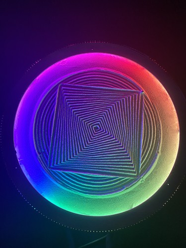
And here is what it looks like:
It’s like it is slightly over rotating for each progressively bigger square? Any ideas?
Hmmm. That is strange.
The stepper motor moves exactly 200 whole steps per rotation. Not 200.01 or something. The gears have an exact number of gears. It can be 320, or 319, but not 319.5. Maybe count the gears to be sure? The drvs are very precise. Unless some of the steps are triggering too fast and they are being missed? Is there anything that can slip?
The software is a big unknown. There could be rounding errors. But I think that may affect intermediate values, but it shouldn’t affect the absolute position that much. The delay math involves some very small numbers. But the total distance traveled is based on the number of steps, not the delay.
I don’t think there is any slipping as far as I am aware.
I am almost certain that the number of teeth is 20/320.
Is it possible that the 1/32 microstep is the problem and the python code can’t keep up with the rotational steps?
I tried charging the 3200 in the theta calculation to use both 3150 & 3200 and it seems like moving either directions makes the issue worse? Too much change and I should try like 3198 or something?
Whoops I meant I tried 3150 & 3250
If you take off the drv8825s and look, there should be three jumpers under them. Remove the outside ones and leave the middle one. That is 1/4 microstepping. Then change the code back to 4 and see.
I can’t explain it with the microstepping, but there are many things I can’t explain and it is something different from the working machine.


