This is where I fail, and I know it. I need this for printing and cnc. 2 days later, I know I made a change, what was it, I saw that somewhere, where was it. Those things bite me and I need to get better at it!
old age is creeping up on me more and more, LOL
2 Likes
So get creative, maybe make a hollow table, if you need deeper, or make an end with the rails that spill out so that you can run past your table! (if I ever get around to lr3, I will have this option. I was just watching people clamp to the end of the table and do Mortising!)
C) Tuning and heat are hand in hand, the more you turn up your drivers, more heat you produce. So to tune, you turn up or down relative to heat/load on your steppers.
E) good bits and size of course, a 1/4" takes more to run than an 1/8.
1 Like
Increase current to the steppers until the steppers get too hot and melt the mounts or the driver (after a while) goes into thermal shutdown, then back it off a bit.
Realistically, this is hard to get right, and skating closer to the edge is going to decrease reliability, not increase it IMO. Use the default current settings and put a fan blowing on your stepper drivers. Done.
With the default current settings, assuming you have the correct motors, you shouldn’t be skipping steps, even on Z. If you really want to push the limits at the expense of reliability, then you can “overclock” your machine.
Having said that, it does sound like your Z is skipping steps. The standard build can lift a lot of weight so something must be binding. Lubrication on the Z screw makes a bigger difference than I expected and I had binding Z when I first built the LR3 and skipped the lube.
Stepping back and looking more broadly at the situation I think the key is not to look for a stock fix (bigger motors, etc.) but to diagnose your specific problems. We are here for you and once you work out the kinks, which can be different for each build, your existing machine can be very convenient (auto-squaring) and reliable.
1 Like
Any of the upgrades that were that easy are already part of the “standard” machine. Everything after that requires a lot of thought. It isn’t just Spend More → Get More, unfortunately.
1 Like
I would simply build another one!
3 Likes
I don’t think that has changed much from LR2 to LR3. If you build it with a huge gantry and you’re 5" off of the spoil board, there is going to be an awful lot of leverage and you will have to really baby it. I wouldn’t do that on an LR2 or LR3 unless I was doing laser or foam work.
The designed file as “standard” are height limited by default. Some forum members have built them longer.
A drop table is going to work better than that though. And you won’t use a 5" bit (unless you are cutting foam) anyway. My table has a section with a vertical mounting surface and I built the hole about 12" wide. So I could carve the front of a drawer or something. I’m sure you can come up with something that would work.
It is a common joke here too. It is legitimately annoying though. There isn’t an upgrade that I know of. There are Z motors with integrated leadscrews, but if you get even a fraction of a degree off of aligned, they will bind bad.
Your drivers are sending a specific amount of current through each motor coil. The amount of torque that motor can “hold” at that position goes up when the current to the coil goes up. If it slips, it sounds like crunching gears, but it is really just the motor jumping to be aligned with another magnet.
If you increase the setting on your drivers to send more current to the motor, then it will hold more, and you will skip steps less often. Even 50-100mA can make a big difference.
How to actually adjust that depends on which controller you use.
If you make it higher, then the drivers will get hotter and the motors will get hotter.
If the motors get too hot, they will make their plastic mounts soft and it will deform. The rule of thumb here is at or below 50C on the motor case is fine for PLA.
If the drivers get too hot, they will protect themselves. The SKR/TMC drivers will lower the current. It can go from 900mA to 700mA if the drivers are too hot. That will cause you to have less holding power (possibly without noticing). The drv8825s will just shut down if they get too hot and they won’t turn back on until they cool down a lot. IDK what the RAMBO does.
So essentially, cool down the drivers, and then adjust the current up while measuring the motor temperature. If the motors get close to 50C, stop, or go back down. The SKR/TMC drivers will tell you if they get over temperature. I have seen a print statement like, “OT Warn, reducing current to 768mA”. And there is a flag in the response from M122.
The 24V thing is harder to explain and understand. But when steppers rotate quickly, they “push back” on the power supply. If they push back hard (because they are rotating a lot), then a 12V power supply might not have enough voltage to get the current you set. This only happens when the motors are moving fast (in terms of RPM, not millimeters). Smaller wires and longer wire runs make this issue worse. The Z motors move 4x faster than the X or Y, because they are driven by a leadscrew.
To be 100% clear, the default settings in our firmware is at a comfortable, safe value for most environments. People who are just building their CNC or are just learning shouldn’t mess with this stuff if it isn’t causing problems. The juice isn’t worth the squeeze when you are also learning.
Anyone else reading this, don’t just take this advice and run with it. It really is situation dependent.
2 Likes
But they ARE very pretty! ![]()
5 Likes
Or fortunately, I guess. Shudder to think how much time and $$ I’d spend if I thought it would get me more speed, depth, finish quality, etc.
2 Likes
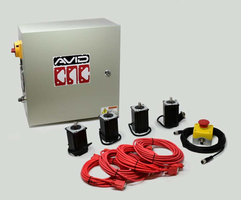
Someone mentioned Avid so I spent a while on their site. It is actually a good example of what prompts me to post this question in the first place.
I looked at the Avid 48x96, which should be very comparable to what lowriders are capable of size-wise. What makes this machine cost $19,000??? It has Nema 34 motors, but you can find those for under $50 each online so that is what $250. It has all the channel aluminum frame, but there is no way that is more than what $3,000, so the only thing I can see that makes it worth the value is the control system. They have what looks like a pretty slick plug and play control system. What is really in that box?? Is it worth $15,000???
My point is there is a TON of knowledge in this crew. Can a design be put together where a budget of a couple thousand dollars that can actually compete with a $20,000 machine? You see it all the time on youTube videos where someone compares some $100 tool to a $10,000 tool and the $100 version does just as good. It could be a great ‘challenge’ on here to develop the next level or lowriders big brother. The challenge should require that the parts are built using a Lowrider and as many wood components as possible to keep cost down.
I am sure Avid has put a lot of engineering and make a great machine, but I feel like there is a good chance Avid is selling a LOT of blue sky at the same time.
1 Like
The $19,000 pays for non-recurring engineering. The parts aren’t the cost, it is the design choosing and testing the parts. The development of the software, electrical and mechanical engineering. Because that is expensive labor and it is split over each kit, but they are custom (or nearly) kits. There aren’t many kits to divide it out. There is more engineering that goes into a samsung TV. But they sell millions of TVs and tens of thousands (I’m guessing) avid CNCs.
You also get support for that money. If your business is using that $20k machine to make parts for customers and they have deadlines, you are also paying to have avid on the phone if your machine isn’t working. Those smart people available all the time cost money.
You won’t find $15k in that controller. At least not without considering NRE. That said, you can’t develop one controller from scratch for $15k. Not even the grbl software would cost that.
2 Likes
I know right, have you seen this joker comparing LR3 to an AVID CNC… This dude is a bit misleading, he mentions cuts being slower, but doesn’t acknowledge the beefier hardware, engineering costs and nice metal controller box that AVID has. Guy’s obviously just a hobbyist/DIYer.
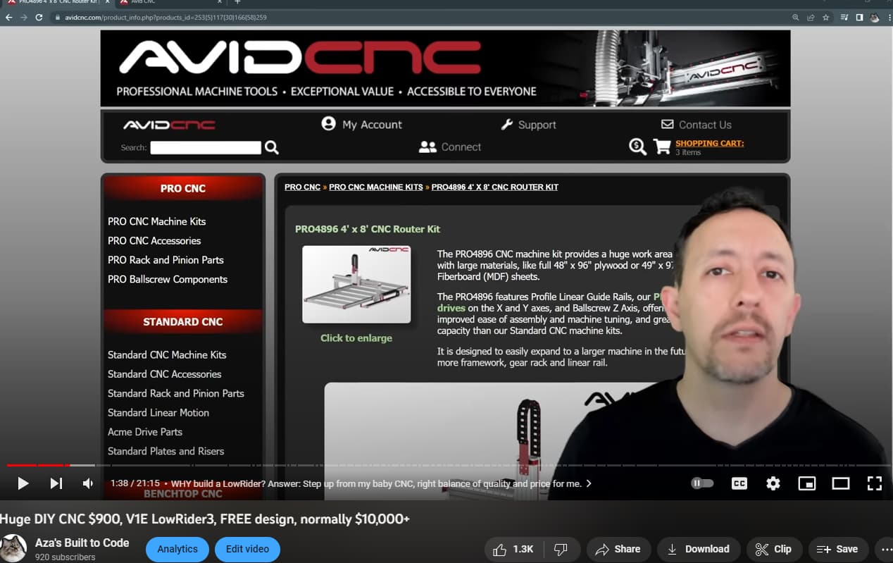
5 Likes
It can take a lot more in engineering and materials to make a machine a little better.
To me engineering is the process of making trade-off choices in order to get the desired end result. Good engineering ends up with no real weak points, so that if there actually is one common point of failure, and thst gets upgraded, the next weakest link comes up pretty quickly after that, and the next and so on.
So with the LR, that means upgrading what you may view as a weak point (let’s say for the sake of argument the NEMA 17 motors) and you upgrade them, the next point of failure becomes evident before much performance increase can be observed. I would think the printed plastic, steel tube rigidity, beam structure, or the GT2 timing belts are likely culprits (assuming one of those isn’t already the actual weak point limiting the machine. When you have upgraded everything (and have an entirely different machine in the process) to get a significant performance upgrade you also have an entirely different price point.
I believe the V1 machines are designed for affordability, and a good enough working capability for hobbyist use. While I’d love the capability that comes with a $20k price tag, I sure wouldn’t have a couple of those in my basement to putter around with. I could have ended up with one of Joe’s CNC machines, and nearly did, 15 years ago. If I’d had a couple hundred dollars more in the hobby account at the time, it would have been so. Those machines are capable of more speed than most V1 machines, but come with the higher price tag and are a little less DIY for building. I would have had to buy more with much higher shipping charges to build that machine to start. (I’m actually considering one again, since now I have a CNC that can cut the parts to build one, now. Just… I don’t really need it, since I have a CNC that works more than well enough for what I need.)
My LR3 started with the beam made for 1/2" conduit, and I saw the increase in rigidity jumping to 1" steel tube, but I still have that conduit beam. I’d use it for a laser in a heartbeat. I saw that as a worthwhile upgrade. I do see a weak point in the single X axis motor, it seems to be the most likely place to skip steps. I was thinking of a way to mount a second motor to engage the belt… but bumping the current to the single motor has done the trick so far, and so I am not really worried about it.
GRBL goes a ways up from where we are, and FluidNC does too. Marlin still has some left in it, I think, too. I am using RepRap Firmware, for the use of machine coordinates vs Workspace Coordinates (Marlin technically supports this, but it’s clunky IMO) GRBL does it too, but RRF is more familiar to me, therefore I use it. I also had spare Duet boards that I could use for my Primo and my Lowrider both.
Honestly the NEMA 17 motors aren’t a limitation. You can get these with more torque than many of the NEMA 23 motors out there. Most.of pur boards support 2A current, and we use less than 1A for temperature reasons. Get some big NEMA 17 motors that can handle 3.5-4A and feed them 2A and they would have a lot more available power, enough to start breaking parts on the machines.
I keep thinking of the rack and pinion setups out there. The LR could be changed that way, I think without a huge redesign, but is it an upgrade? Well… maybe. And maybe it’s just exchanging limitations and problems. Backlash is a thing, like belt stretch. Once again, this isn’t really a weak point of the LR design, IMO
I built a Primo first. I see advantages to both formats, and drawbacks. I think the LR style has a lot of low cost advantages, in that it delivers more rigid performance at a much lower cost to build. The traditional gantry needs more material at a higher cost to deliver the same cutting rigidity at the lowest level (ie: cutting through sheet goods) so it starts to depend on what I use the machine for. I would have very different needs making aluminum cylinder heads for engines than my typical use case of cutting shapes from plywood. I’d also have a completely different budget, but that’s another matter.
I am still often tempted to change the one conduit rail out for a fully captured version. The conduit rail has caused me some issues in the past (which were really other build issues in disguise.) That a fully captured rail would have just solved. The use of a single rail instead of two rails is actually a good thing, though and makes the build easier and more tolerant of many of the issues I actually had. Some of those would result in the machine completely binding up.
Yeah, but even a “cheap” tool changer comes with a hefty price tag.
So if I could spend more? Probably I’d buy other shop tools, have centralized dust collection, and maybe a shop crane to load material onto the tablesaw and CNC.
2 Likes
As I said twice: the Volksfräse does it. It costs twice as much as the LowRider but should be able to match the Avid. I pondered building it but uncle Phil is going the clickbait route with videos where he is only talking.
With the Avid you pay for the plug and play ability basically. There was a video somewhere of a guy who built his own 20k CNC. That one was impressive in every way.
1 Like
If you figure that one out it would be great. Primoish trucks on Y would be great. ![]()
Curious what issue/cause you ran into? Personally ran into issues with bearing embedded within the rail roller parts going off the EMT rail as the gantry moved between Y min and Y max. For my situation, underlying cause was that I hadn’t positioned and squared up the belt holders correctly.
Unexpected air gap between the bearings and Y axis EMT rail was so tiny that I only noticed a few months ago when chasing square sub millimeter accuracy to cut MP3DP panels. Started wondering about monitoring/compensating for this type of problem without changing design.
Pretty much same. A line wasn’t quite straight because the bearings were wandering a bit on the rail. Less than 1mm, but noticeable on the part because it was a long dado. Temporary solution was a 2L pop bottle full of water put on the rail side YZ plate, and reduce max Y accel. More permanent solution was to fix the slightly off square XZ to beam join when I installed the steel XZ plates.
1 Like
closing old topic to help fight spambots