The $10 set should do you for the rest of your life, unless you go into production making circuits!
2 Likes
Hi Steve, Is there a particular reason you went with a unipolar option over a bipolar sensor?
2 Likes
I’m still hoping to get clarification on this.
In this screen shot:
…the capacitor seems to obscure things, but I guess there are three wires for three leads. I’m foggy on where to get that extra wire connected to ground back at the board. I will figure it out eventually, once my capacitors I ordered finally arrive.
Negative of the power supply would do. Might be some other pin headers that are convenient… I don’t have a board handy to check.
Gnd = Negative for this purpose.
1 Like
@dos Thanks!
I was presuming we were going to use the regular endstop pins only this time we DO want to use the 5v pin as well? Is that not right?
I have a 1st gen JP1 which has the 5v headers populated, which is nice.
1 Like
My parts will come today and maybe I’ll have time to work on it this weekend. I think that I’ll add a small perf board between my jackpot and the sensors where I’ll connect the capacitors and resistors. That way I don’t need to figure out how to fit them in the mounting part that way people who want to use my model don’t have to get the exact same capacitors as me etc. And I won’t need to populate the 5v header because I’m lazy and don’t want to take the board out of its box.
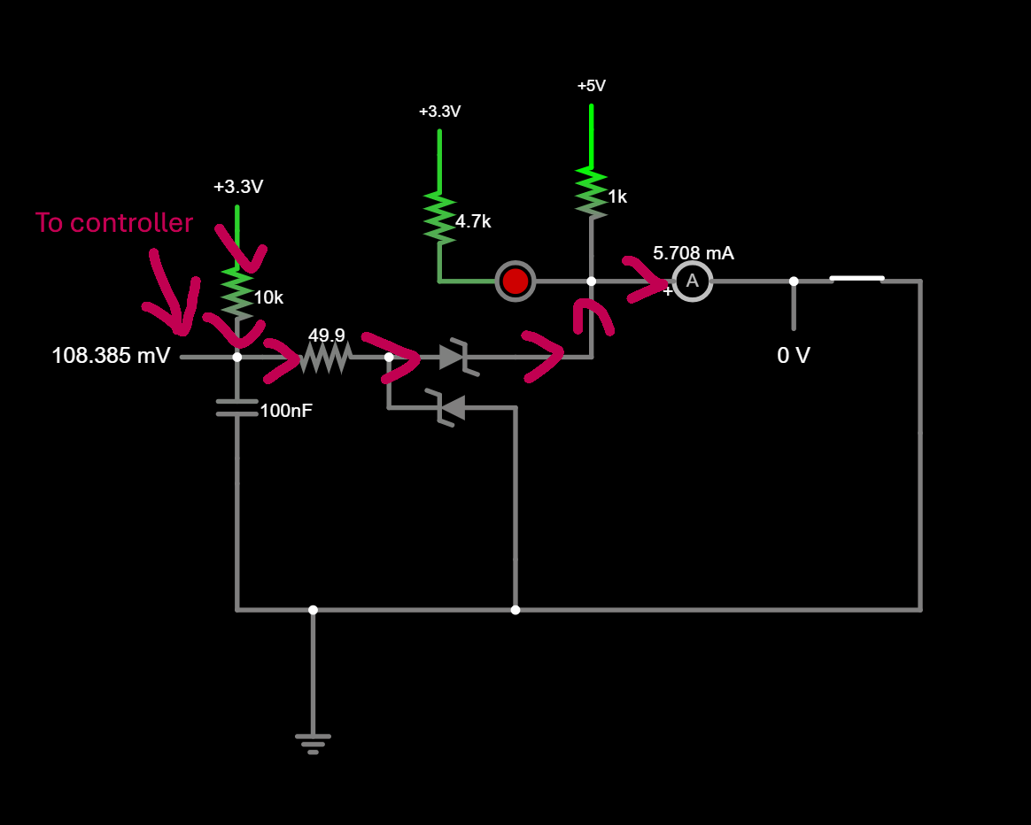
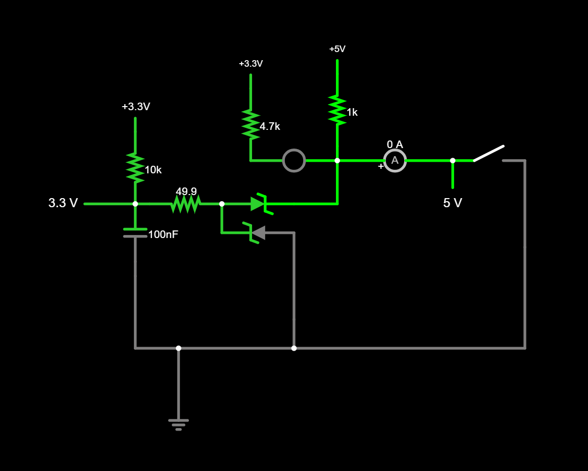
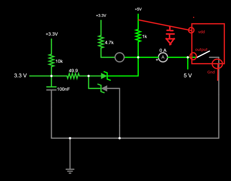
Just for fun I did a quick model of the switching circuit on the jack pot. If anyone is curious you can follow this link and click the switch on and off and see how current flows through the pull up resistors etc. circuit sim. I added the pull up to 5v for the hall effect switch but modeled the rest of it as just the switch for simplicity.
2 Likes
No good reason that I can recall. If you use bipolar, you don’t have to worry about which way to point the magnet.
1 Like
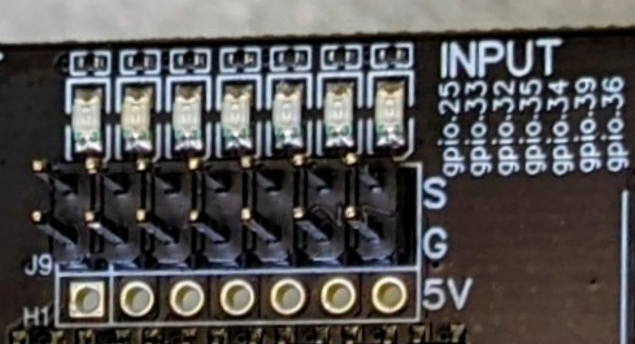
Doug – see the image @Dreyfus posted. Your drawing in pencil would connect #1 to 5V (either by populating the limit switch header pins or by using the 5V pin on the expansion header), #2 to the G pins in the limit switch header, and #3 to the S pins in the limit switch header… and add in the caps and pullup resistors as noted.
1 Like
Do you have any pics of yours mounted in your machine?
How susceptible are these to high emi environments?
They are very immune to noise, thanks to strong (1k) pullup and filter capacitor. I looked at the signal on my oscilloscope – so clean!
Some photos on my Portable Primo:

The resistor and cap are just beneath the pipe there, a few cm from Hall switch.

3 Likes
Awesome, thank you! This finally brings me the clarity I needed, as a half-newbie regarding this electrical stuff. Also, that’s not my pencil drawing, but rather a screen shot from Prof. @stevempotter 's video about his machine.
I love this idea. Sounds like a decent project that could be my first effort at designing a PCB. I’m about as clueless as they come, and my foggymindedness due to decades of sleep deprivation does not help, but maybe I could muddle through it.
This is fabulous, and I’m sure it is helpful, although I’m clueless as to which “leg” of this is what. LOL
1 Like
I assume it’s optimal to have the components as close as possible to the sensor?
Maybe this helps. Basically what this component does is connect the output to ground when the field is sensed.
I love this idea. Sounds like a decent project that could be my first effort at designing a PCB. I’m about as clueless as they come, and my foggymindedness due to decades of sleep deprivation does not help, but maybe I could muddle through it.
It would be a super simple circuit. It will basically need to be just a breakout for ground and +5v plus a 1k pull up resistor for each signal path. And as I’ve been thinking about it today I’m coming back around to maybe trying to house the cap and resistor in the printed part.
2 Likes
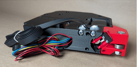
Curious how people already mounted hall effect sensors to their LR4, especially Y end-stops?
Blob of hot glue, or, small printed part that mounts to existing M2.5 holes where microswitch normally mounts, or, did someone already remix front roller part to house recessed sensor, maybe curve front to self align when skewed for whatever CAM/operator fluff-up reason(s).
Guessing anyone exploring this path is driven by the want for more hardy robust Y end stops?
Current end stop’s precision and accuracy are fine. I don’t recall seeing posts sharing concerns with microswitch based X and Z axes.
Check out this post!
My fist thought (which is almost always complete overkill) was to 3d print some kind of housing with the same form factor as the original switches so you can just drop in replace them. The sensor’s resistor and cap would live in the housing too… maybe pot it!
1 Like
That was my thought too.if you’re making a custom pcb it would be the same footprint - including the m2.5 holes with 3 components and either pcb headers or a XH JST socket
2 Likes
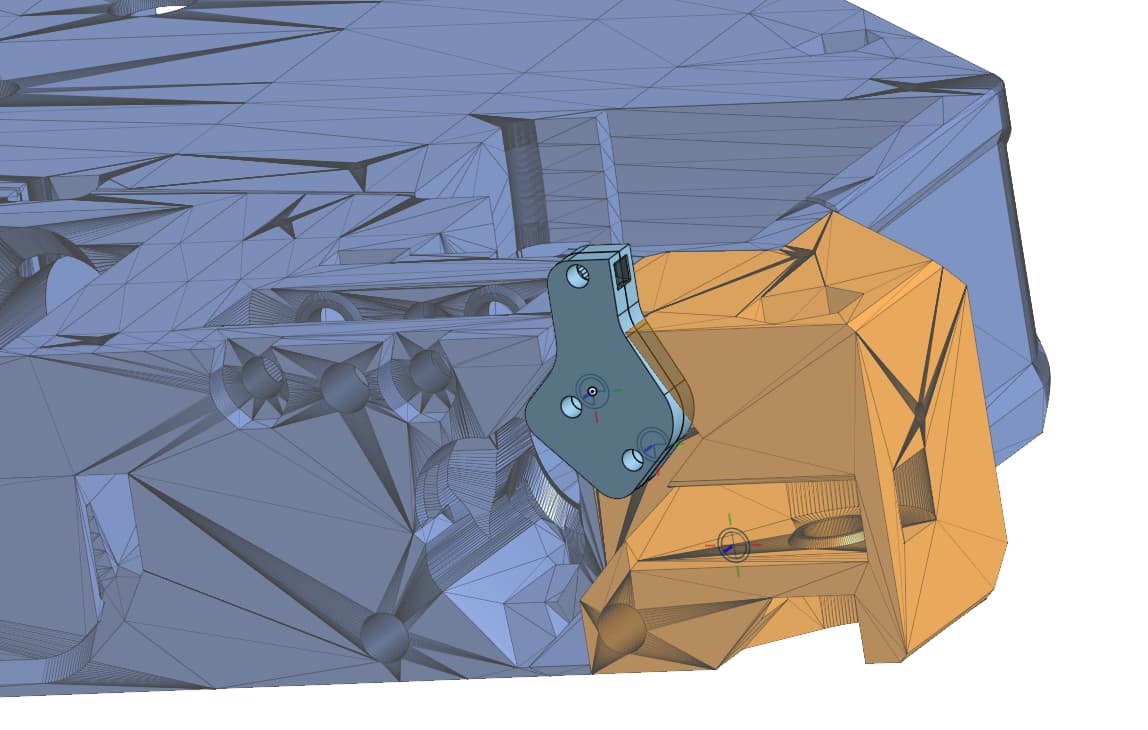
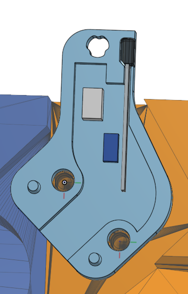
Here’s a new version of a mount onshape document. It prints in two parts. The gray and dark blue shapes are outlines of the resistor and capacitor I have on hand to use for this. I think there’s enough room for people to jam whatever in there then slather everything in hot glue select and mount components meeting their quality control standards. It will print in two parts and use the regular mounting holes and screws then one m2.5x ~6mm screw on to clamp the top end on.
6 Likes