So I just found this article that has helpers for designing for 3d printing. Some of you advanced peeps may find it boring, me, it is quite enlightening. It was so good, I actually found it on the Freecad blog!
Hope you enjoy!
So I just found this article that has helpers for designing for 3d printing. Some of you advanced peeps may find it boring, me, it is quite enlightening. It was so good, I actually found it on the Freecad blog!
Hope you enjoy!
Great info and very helpful.
I like the part on chamfers vs fillets. I have been starting to use those strategically and it makes a big difference.
This article really explains the why of certain design choices.
That is fantastic. That seems 100% complete as well. I bookmarked your post so we can share it more easily.
Great find, thanks for sharing.
Wow, great resource. I’m reading through
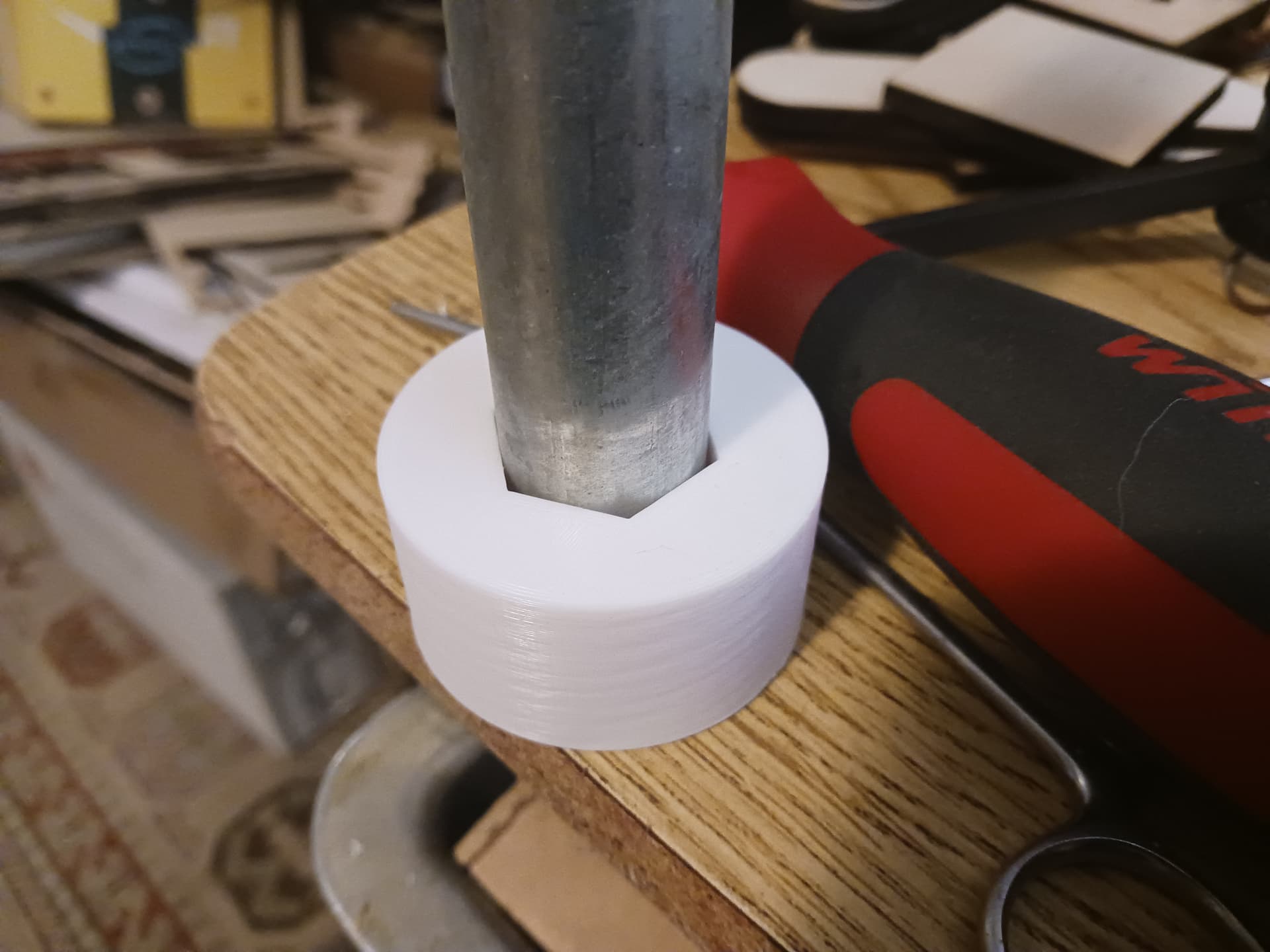
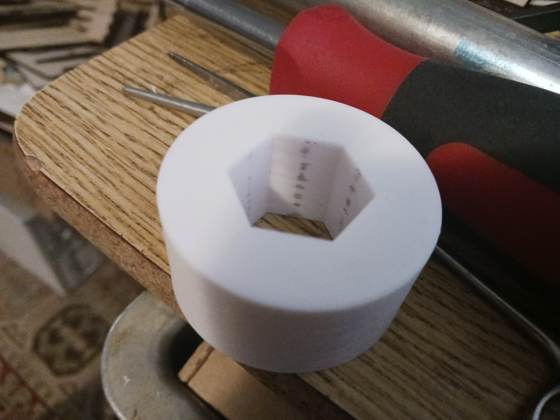
This really is a fantastic write-up… and timely, too! I really appreciate the section on “holes” that really shouldn’t be circular… as they can only “stretch around their entire circumference” to accommodate an interference fit. Hex, on the other hand, can flex radially in a far fewer number of points of contact, to accommodate a larger amount of interference… which is exactly what’s needed to address the differences in EMT conduit diameter and 3d printers.
So, I printed a test part…
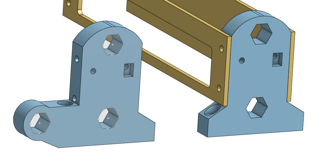
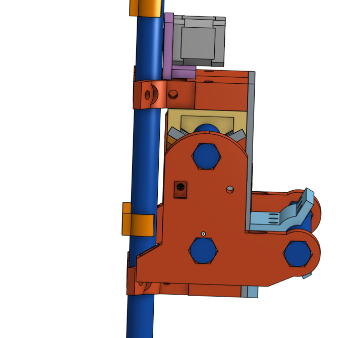
Given this information, I guess the MPR&P end supports should look more like this…
It’s definitely quicker and easier to layout in CAD vs the flexible fingers of the compliant hole… and a lot less small detail the printer will need to accommodate.
Good stuff!
I was going to ask if rotating the hex 30 deg would make them easier to print, but nevermind. These parts print on their sides…
Adding a little radius to the corners of it will save a bit of time printing.
That link is full of all the things it took me all these years to figure out. Priceless resource.
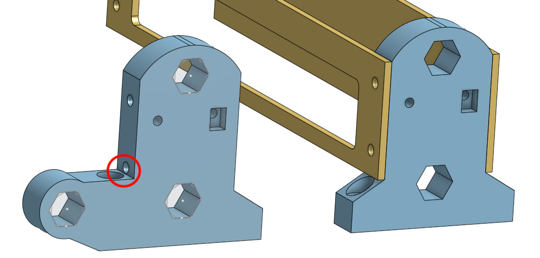
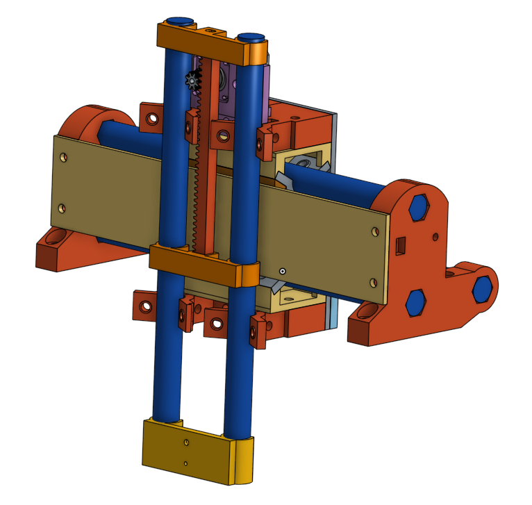
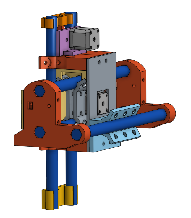
Hey, Jim! These end support pieces are derivatives of one another in my CAD and when I put the holes for the Y side plates in one they appeared also in the other. I’m not sure the gantry really needs the side plates since it has the third conduit already but since holes magically appeared I was interested to see if there was room for a solid side between the Z rails and the gantry. There probably is, if the side plate is thin enough…
It would be pretty easy to add relief or a recess for the bolt head or nut if we thought the side plates were really necessary for the gantry… but I just haven’t carried through with it one way or the other. I can just as easily plug them (or prohibit their creation) if they aren’t needed.
Since my prototype machine is operational at the moment, I’m just lazy and reluctant to tear it down yet again to add in these latest changes that are more for easy duplication than added functionality. I’m also trying to clean up my CAD files now that it’s starting to take shape.
You mentioned that you may still take your MPR&P to the show… can you DM me a brief status and/or a photo or two of your machine? I’d love to see it.
– David
I’m still debating this, and need to chat with Ryan about whether there is room for a work in progress. I’ll let you know. Keep an eye on the RMRRF 2025 thread!
If there is room on the table I would love to see it! I am a little unclear about how much table space we will have but the more the merrier.
It’s now later and it’s a fantastic read. ![]()
Superb summary, I actually think better than the “Design for Additive Manufacturing” module of my degree (that was mostly someone waving their generative design tool around at us ![]() )
)
I haven’t tried it (yet) but the author has created a FreeCAD add-on to make it easier to create some of the suggestions.