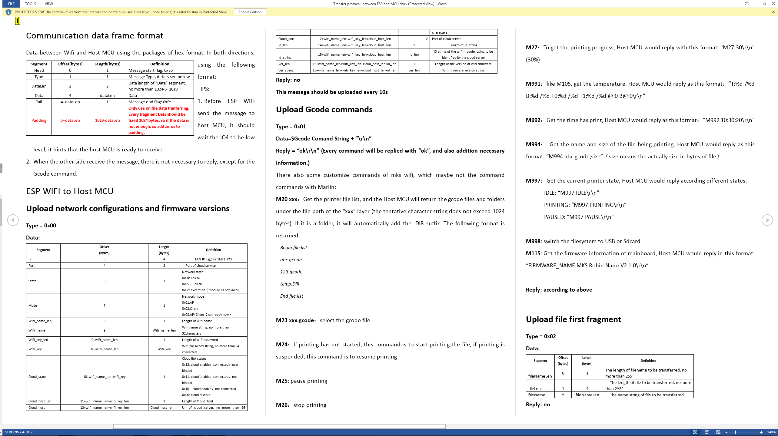
I figured I would put this here because I’ve seen more than a couple threads where this has been brought up. Yes, there are TFT touchscreens that work with GRBL. Here is what I have personally tested…
TFT
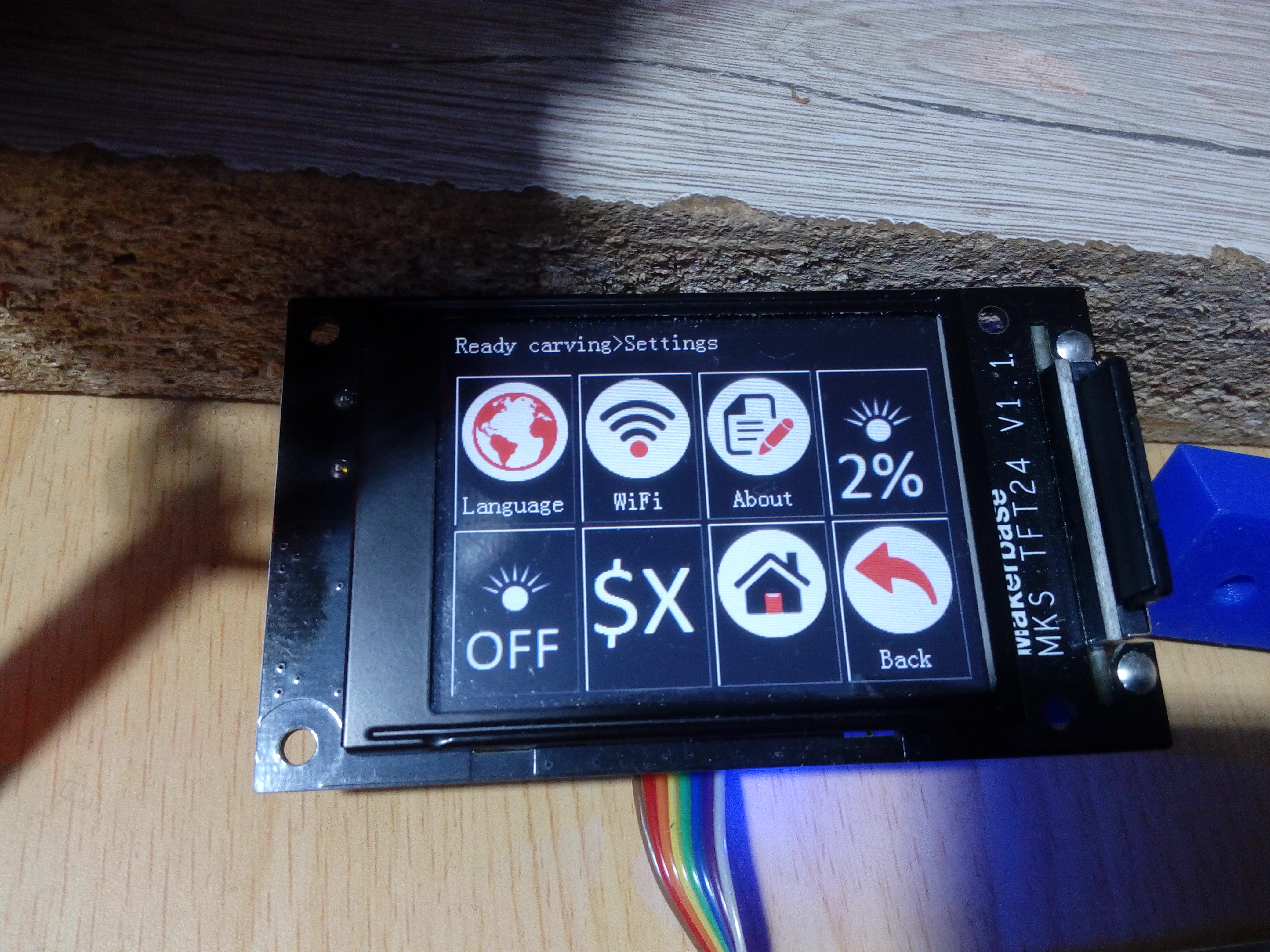
-MKS_TFT24
Boards
-MKS_DLC
-UNO/CNCshield v3 stack
-RAMPS stack.
Firmware
-RAMPS - GRBL-Mega5X 1.1q
-UNO and DLC - GRBL 1.1h
-TFT - MKS_TFT24_CNC_V1.0.1
Here’s the link to the TFT firmware.
Q and D tips
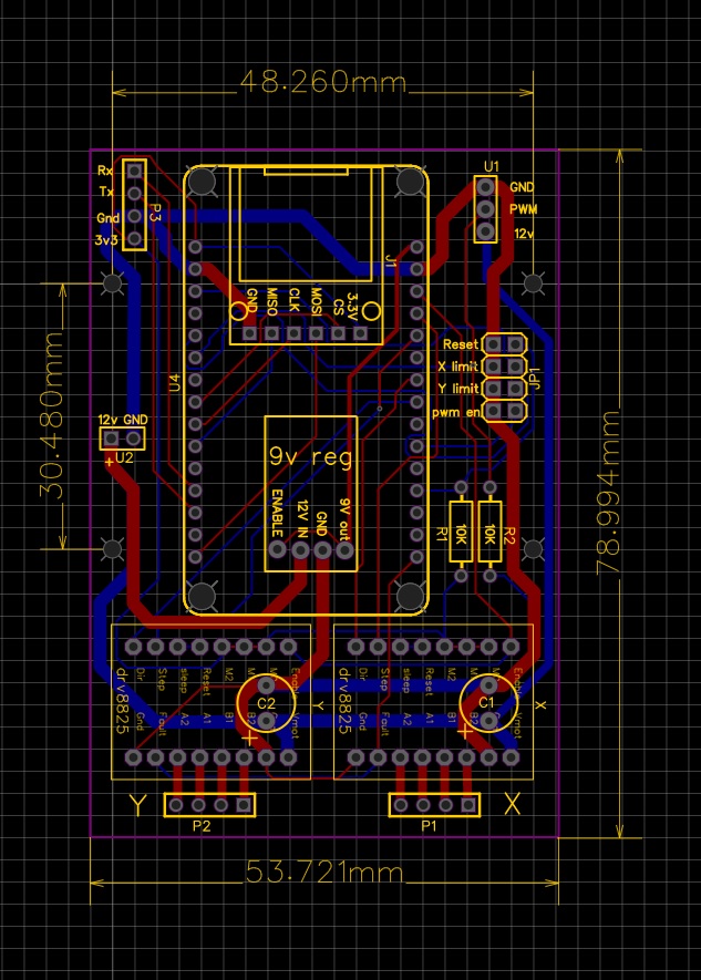
The TFT connects to the DLC and the RAMPS boards to AUX1 via an 8pin ribbon cable. You cannot use this cable to connect to the CNCshield board due to the different pinout. You need to either make a custom cable, or just use 2x2, or 4x1 Dupont cables. You would connect to the 5V and GND, and the TX/RX pins on the header above the end-stop header.
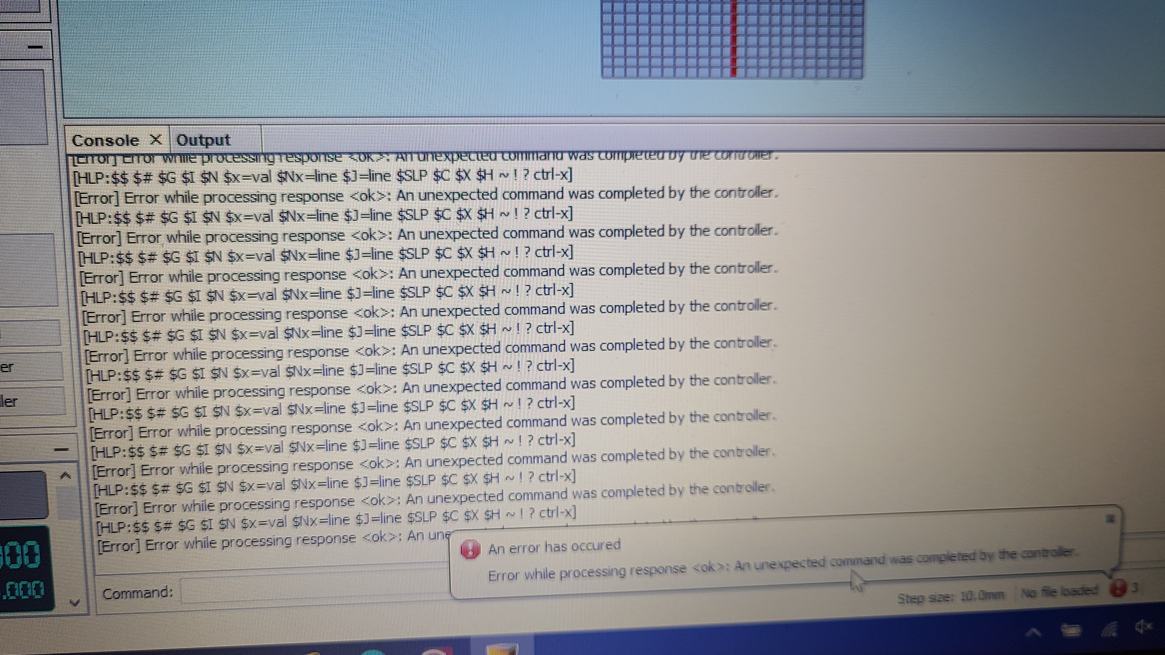
From what I have experienced, when using the TFT, you cannot have the USB COM connection in use on a connected computer because they share the serial line. You can have it plugged in, but not have any software connected to the COM port. Doing so causes random, unexpected comm errors and will usually cause your running job to fail. Now I think the RAMPS stack has multiple assignable serial ports, so that may work.
Since the CNCshield sources 5V from the USB, you would have to use the USB as a power source, or connect 5V to the board another way. And, if you thought ahead to avoid ruining the VR on your cheap MEGA2560 and removed the D1 from your RAMPS board ![]() , you will have to supply 5V to that as well through USB or otherwise.
, you will have to supply 5V to that as well through USB or otherwise.
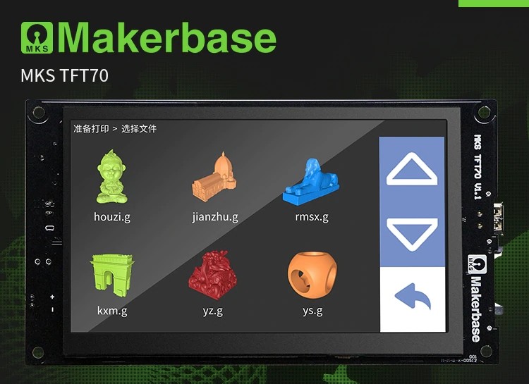
Now Makerbase makes two other TFTs that support the CNC firmware. They are the TFT32, and TFT35. Remember, these are MKS TFTs, not BTT TFTs.
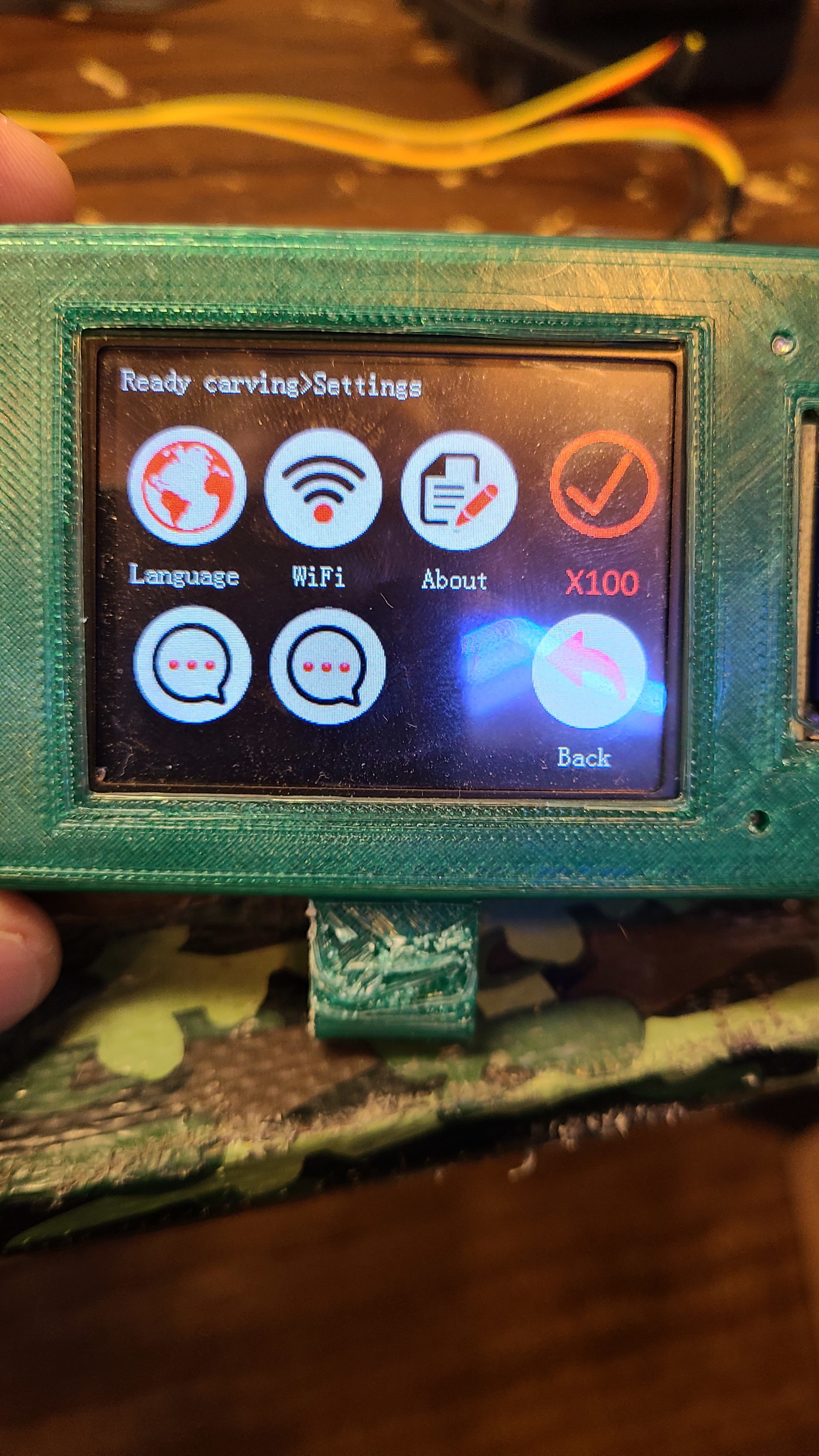
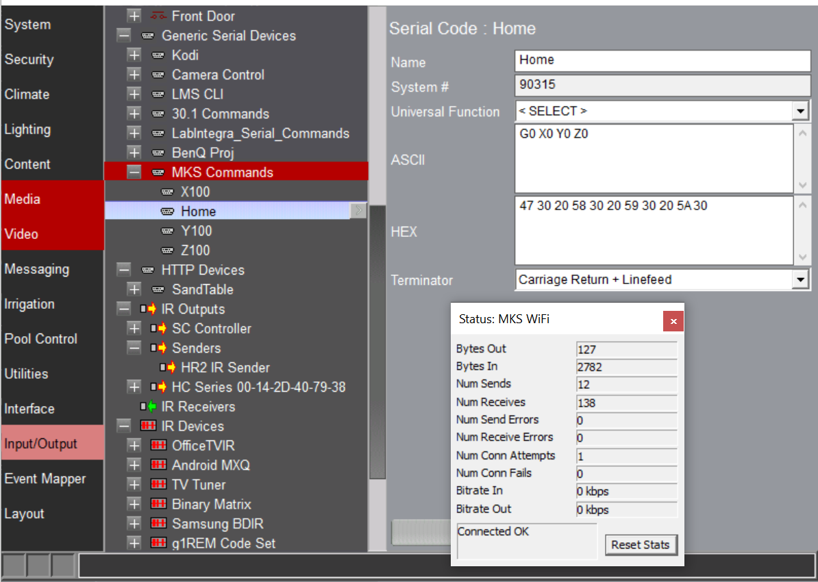
The TFTs have icons for homing, setting home, axis movement, spindle/LASER ON/OFF, spindle speed/LASER power, relative feed rate(%), SDcard file access, and also has slots for custom commands you can add by editing the config before loading the firmware to the TFTs.
My guess is that these TFTs will work with any board running GRBL that has a serial header on it.
PICS
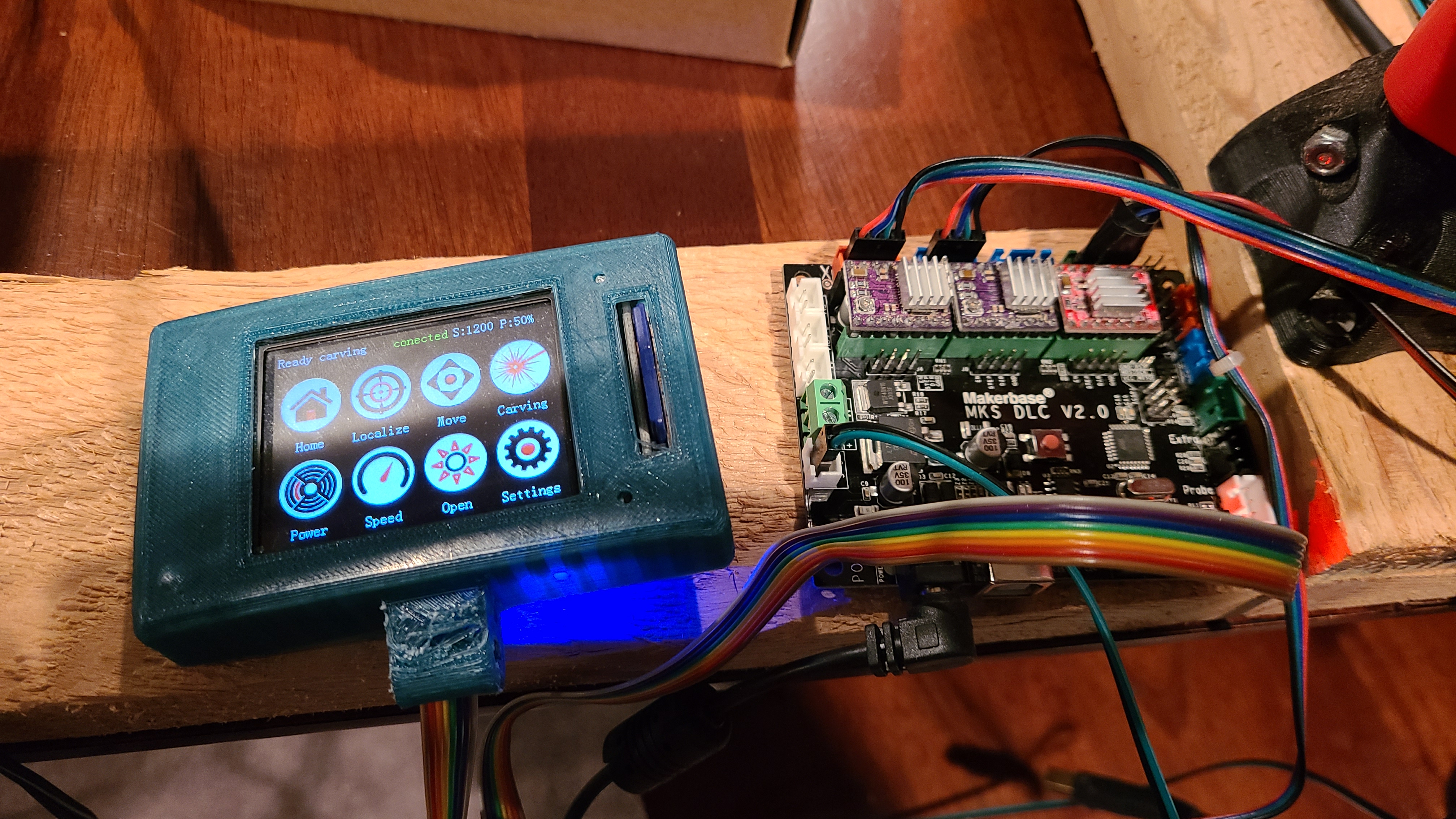
MKS_DLC
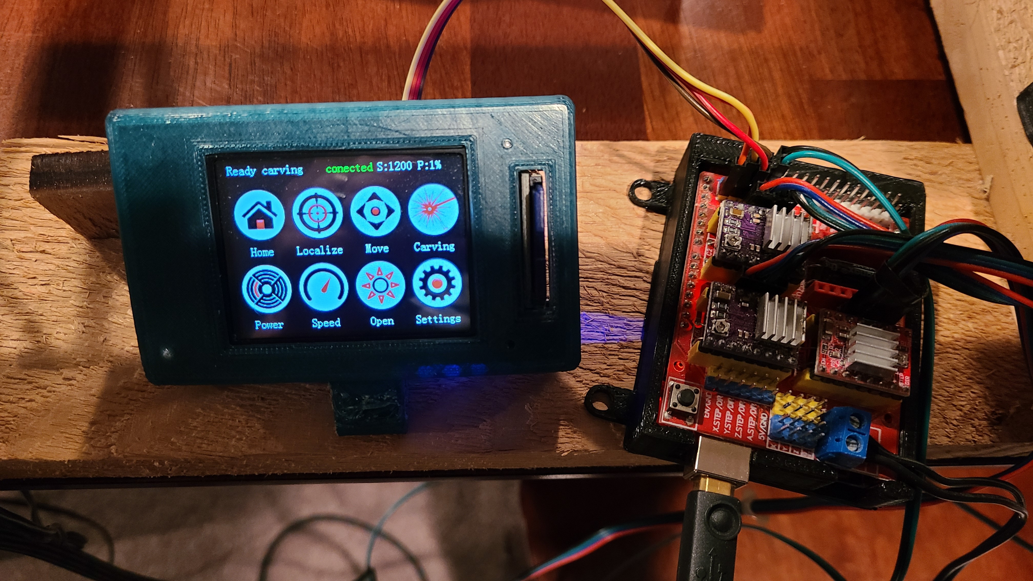
UNO/CNCshield
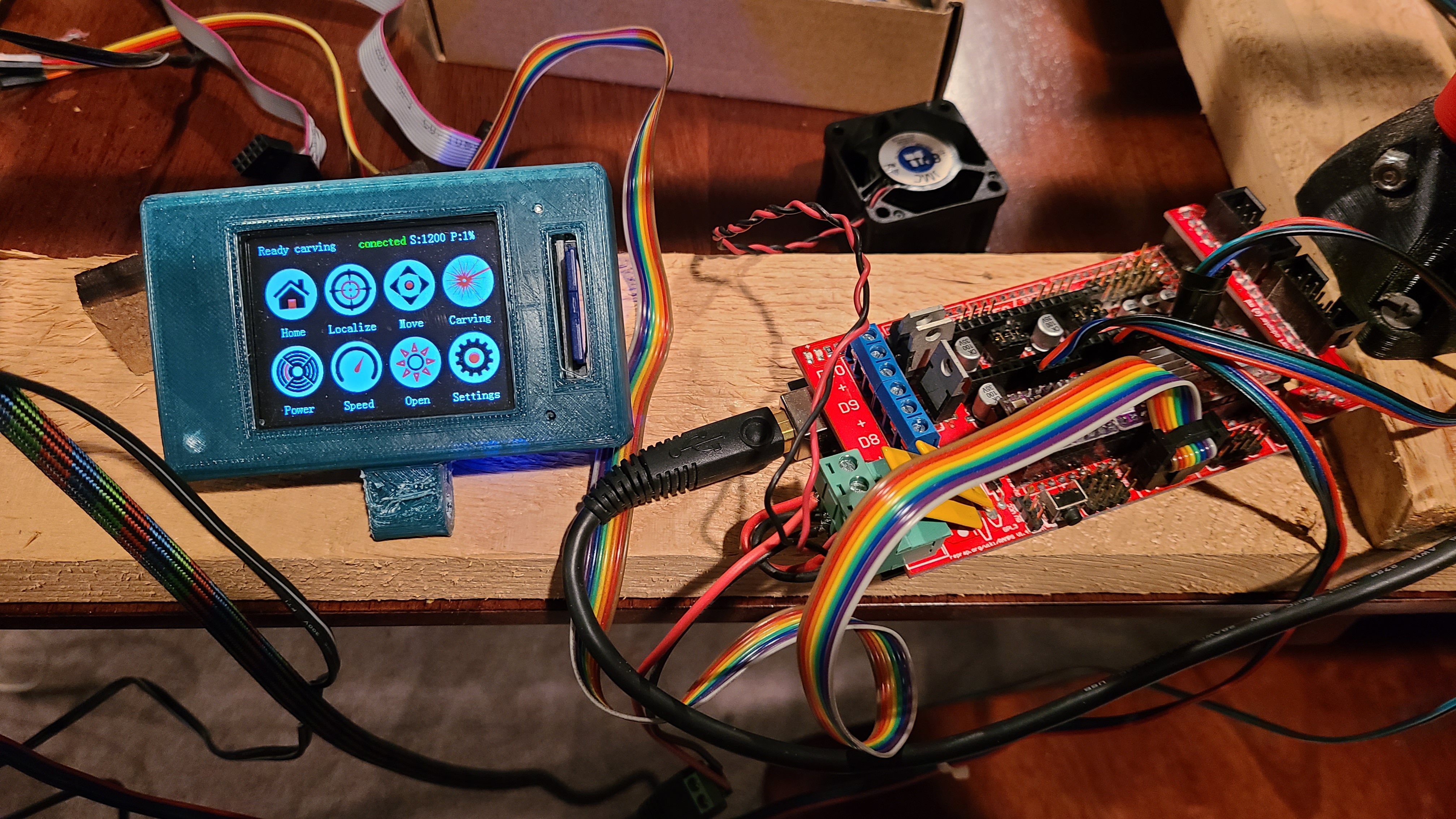
RAMPS
So again, just thought I get this started. Please add to it!
 and decided it wasn’t worth it.