Golden Primo First build

Here is a bit more information on what Jeffeb3 is suggesting on the other thread with respect to your E Stop switch. He proposes purchasing an IoT relay like this one: https://smile.amazon.com/gp/product/B00WV7GMA2/ref=ppx_yo_dt_b_search_asin_title?ie=UTF8&psc=1

You could wire it up like this:


Note the E Switch would be positioned right where you had it in the picture in your initial query and only needs to interrupt the 12v line. Short term, there is little benefit to this solution over interrupting MAINS power. Longer term, this solution can be upgraded an no cost so that the signal line uses one of the fan output pin sets and then you can control your router through GCODE. So with a bit more work your router and maybe a small vac would start automatically when the job starts and stop when the job ends. A search of this forum for “IoT Relay” will give you more information.

2 Likes

I might try this! I really like the idea of the router starting like that!

Just to confirm an IEC cable to the same “Mains” as the 12v converter would work for the IoT?

1 Like

Yes, you can use the same extension cord to power both. Note that the signal wires into the IoT draws very little current so they can be light duty. I used 6’ of 22 AWG speaker wire for my IoT relay. Also there are power pins on the Rambo board you can use rather than splicing into the power cable as I have it in the diagram. The benefit to using the pins is that in the future when you want to control the IoT Relay by GCODE, all you have to do is move the connection to new pins. You will need Dupont connectors to connect to the pins. I would recommend getting pre-made wires with connectors and then cutting and soldering to make the connection. There might be wires left over from the Rambo board that you can re-purpose to make the connection to the board.

1 Like

I already got a dupont kit and crimps just in case and I think I’m going to redo all the wire lengths to clean things up at the end. Haha I was thinking of the extra wire that came with it as I was reading this.

Since I only check this forum sporadically, let me go ahead and give you the pinouts for the Rambo board that you can use to drive the IoT relay.


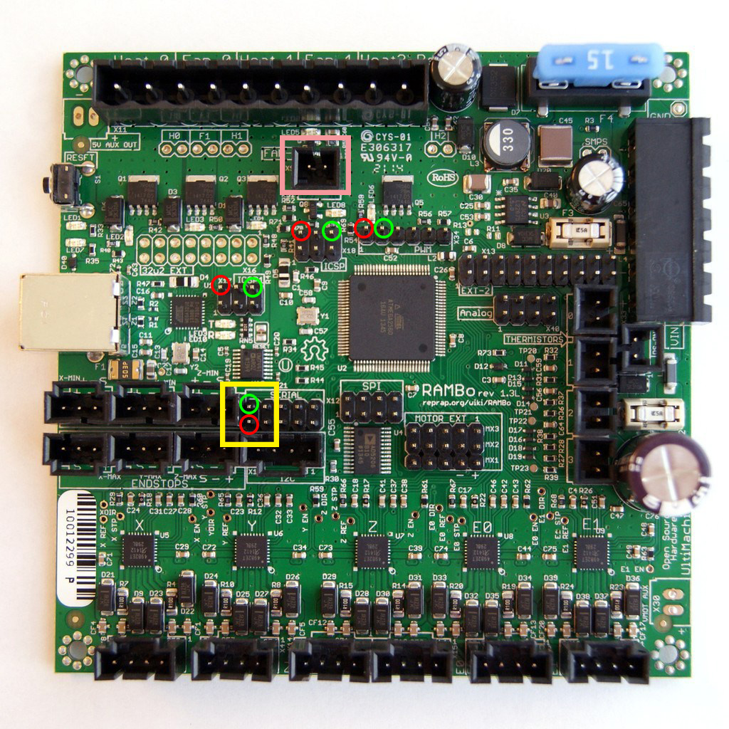
To start, you are looking for pins that are always on when the board is powered up. The two in the yellow square I’m absolutely sure of since I use them for something on my MPCNC. The other circles represent likely power out pins based on the schematic. Note I have limited electronics experience, so you will need to test pins other than the ones in the yellow square with a multi-meter before using. The peach square are the pins I use to control my IoT relay using GCODE M106 and M107 commands. There are other forum posts that cover using Fan2 to control devices. Note you want to be careful to never short out the pin pairs I’ve listed when the board is powered up…you will likely damage the Rambo board. Also the IoT relay connection is polarity sensitive, but, based on other posts, getting it wrong only results in the IoT relay not working…not damage to the board.

3 Likes

Would I be correct in assuming I want to use the power pins you suggest while I’m getting it to a good functioning state then the Gcode manipulated pins once I get to regular use?
Would the router turn off with the E switch in that position while the IoT is connected to the board?

Yes, use the always-on pins to get it working. The method(s) that can be used to create the M106 and M107 GCODE commands will depend on how you send the GCODE to the Rambo board and possibly what tool(s) you use to author your GCODE. You can save this research for later when you have more experience. And yes, the router will turn off any time the 12V power is cut to the Rambo board, so you can wire the E Stop switch in the place you indicated in your original picture.

1 Like

Thank you sir! I am very grateful for all the information and time you have given me. I think I’m going to need something bigger than just the sexy gnarly case.

So I’m hoping to get through wiring this weekend. After that I’m going to need to flash my rambo 1.3 with the correct duel endstop firmware. Hopefully that will be next weekend. Are there any guides, tips or suggestions you guys have or think I should study before I get to that point?

Positive attitude going in, step by step, have fun. If you get frustrated I can give you Barry’s number to call and take it out on. I’ll be busy…until you figure it out.

1 Like

Haha Filling me with confidence already!

1 Like

As someone who just upgraded to Primo and installed dual endstops for the first time, here are a few thoughts.

The latest Marlin firmware has become difficult/impossible to build using the Arduino IDE. The problem appears to be too long of a command line. Assuming you have this problem, you can try moving all the code to the root of a drive and shortening the name Marlin.ino to M.ino. Or you can instead compile it using Visual Studio Code and PlatformIO. I ended up having to use PlatformIO.

You will likely want to change the following lines in configuration.h of the Merlin firmware to match the size of your machine before flashing your firmware:

// The size of the print bed
#define X_BED_SIZE 200
#define Y_BED_SIZE 200

If you don’t change these values, your homing will fail if the machine is more than 200 mm away from the home position…not a super bad problem since you can always drag the router close to the home position before sending the home command.

As someone who just upgraded to dual endstops, I was very glad I was careful and methodical. Ryan does a good job of explaining, but mistakes here can damage your Rambo board or have you wipe out the endstop brackets. In particular take care to avoid the positive pin when plugging the stops in, note that the firmware that Ryan provides expects the X and Y limit switches to be normally closed, and test your setup both in and out of the home position by sending an M119 GCODE to the machine and examining the return values.

2 Likes

Alright V1 Fam! This is the first chance I have had to share my progress since my last set of images. Here is the table / enclosure I have been working on. I really didn’t put a lot of thought in to it. My main thoughts were to make it fairly easy to work on (lid lifts up on hinges and the entire top is removable if need be), have at least some sound reduction and have enough space to add an overhead vacuum… Eventually. I also wanted to have my enclosure ready when I do the wiring so I can make everything look clean. More updates coming by the end of the weekend hopefully.


I took the primo apart so I could separate the spoil board. I was a little over confident with reassembly and messed up the orientation. You may notice this in the images. I have since fixed this oops. I had to flip a couple trucks flip the core and turn the base 90 degrees… Oops… in the end this made the front left corner home.

2 Likes

Also I made a thing. I think it will do the job

2 Likes

That pen holder should work. The key is flex in Z and not in X, Y. This looks like it work as long as the pen doesn’t twist. At least it will be obvious when it does.

2 Likes

I may have to cut the bottom V shape off in the slicer so i can print a glue it to the top :man_shrugging:

Use it for a bit first. I think it will work pretty good. I have thought about it a bit, and I can’t think of a better solution that Ryan’s. But it can only be printed one way and that limits the ways you can draw the mount. There have been a few with high BOMs, like springs and linear bearings. Those will work, but it would be nice to avoid an order of parts if we can just print a compliant spring.

1 Like

If you use very little pen pressure the deflection will be extremely minimal and work great. My double wishbone suspension just helps when there is lots of surface deviations or excessive pressure.

1 Like

Here goes!