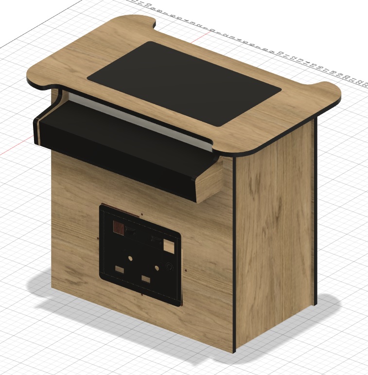
Then modified for a 22" 16:9 monitor and two player side by side controls.
I would like to drop a 4x4 sheet on the table with as many parts that can fit and hit the go button but I’m guessing there are a few steps needed in there somewhere
Small change in direction for this thread–figured I would document each step I took so I would have a record when I invariably forget.
Step 1. (only applies if you are building an arcade cabinet). Get the DXF files from www.classicarcadecabinets.com. The files come in a pseudo cutsheet layout but don’t have all the details you need (depending on the file).
I ended up looking at pics online to get a sense of how each piece fit into the other. I arbitrarily assigned the slots and recesses to be .3" (generally I work in metric but since these are all in imperial, i just decided to stay in that format).
Step 2 was to import them into fusion360 and extrude them all to the depth of the wood I’m using. again I just picked 5/8" ply but it could be anything. The originals often used different thicknesses for tops or some structural feature but I’m trying to make my life easier, not harder…
Step3: Assemble the panels carefully and make sure there are no collisions. Fusion360 has an “interference check” under the “inspect” tab. I also used the “combine” tool with it set to cut and make sure you check the “keep tools” button. This basically uses one piece to carve another.
The next steps depend on how much of a pro you are with fusion–I’m not, so here we are. A pro would have had all clean sketches and all the right bodies in the file already. I had a whole bunch of sketches and little bits and bobs cut off and added on floating around.
This is important because if possible you want to use your finished sketches and convert the whole thing to DXF and there is a built in feature to convert everything at once–I couldn’t figure out how to get fusion360 to ignore the extraneous bit though so I had to do a few extra steps.
What I did was: convert each finished body to a component and then drag all the finished components into a new drawing with no history.
Then each component was laid flat on the XY plane with the cuts facing up. Then select “create sketch” and use the top face of the component as your plane. Then press “P” for project and select the top face of your component–make sure all the geometry gets picked up. Every corner and feature should have a purple line around it–Hit finish sketch.
Then right click the sketch you just made and save as DXF.