You only need to print one brace “reversed”. Just use your slicer to rotate on the horizontal plane so that the bottom becomes the top. That way the top can face outwards on the ends (normal orientation facing outwards on one end, reversed orientation facing outwards on the other end). That is the surface that the XZ plate attaches to. I’m not sure how critical that is, but Ryan recommends it due to surface variations on the bottom layer(s) because of mesh levelling. One XZ plate could be a bit crooked otherwise.
Personally I think the temporary struts is a much bigger issue.
As for the braces it is recommended as print beds can br extremely unlevel. If you have a glass bed you are probably within more than acceptable limits
More than x10
Likely you won’t be able to cut at that speed but it does point out that the issue isn’t strictly speed oriented
Yeah, I was focusing on his PVC, not focusing on his acrylic.
Acrylic + Alchohol = Micro fractures, I feel is not as vast knowledge as it should be. Being around dental acrylics all my life, I’m still surprised to learn this in my 50’s.
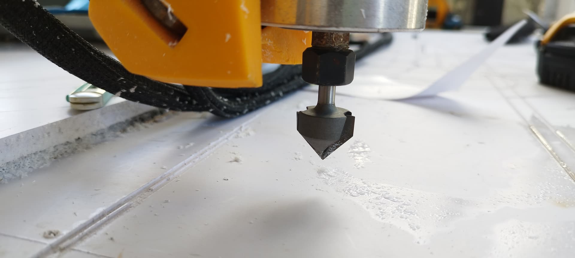
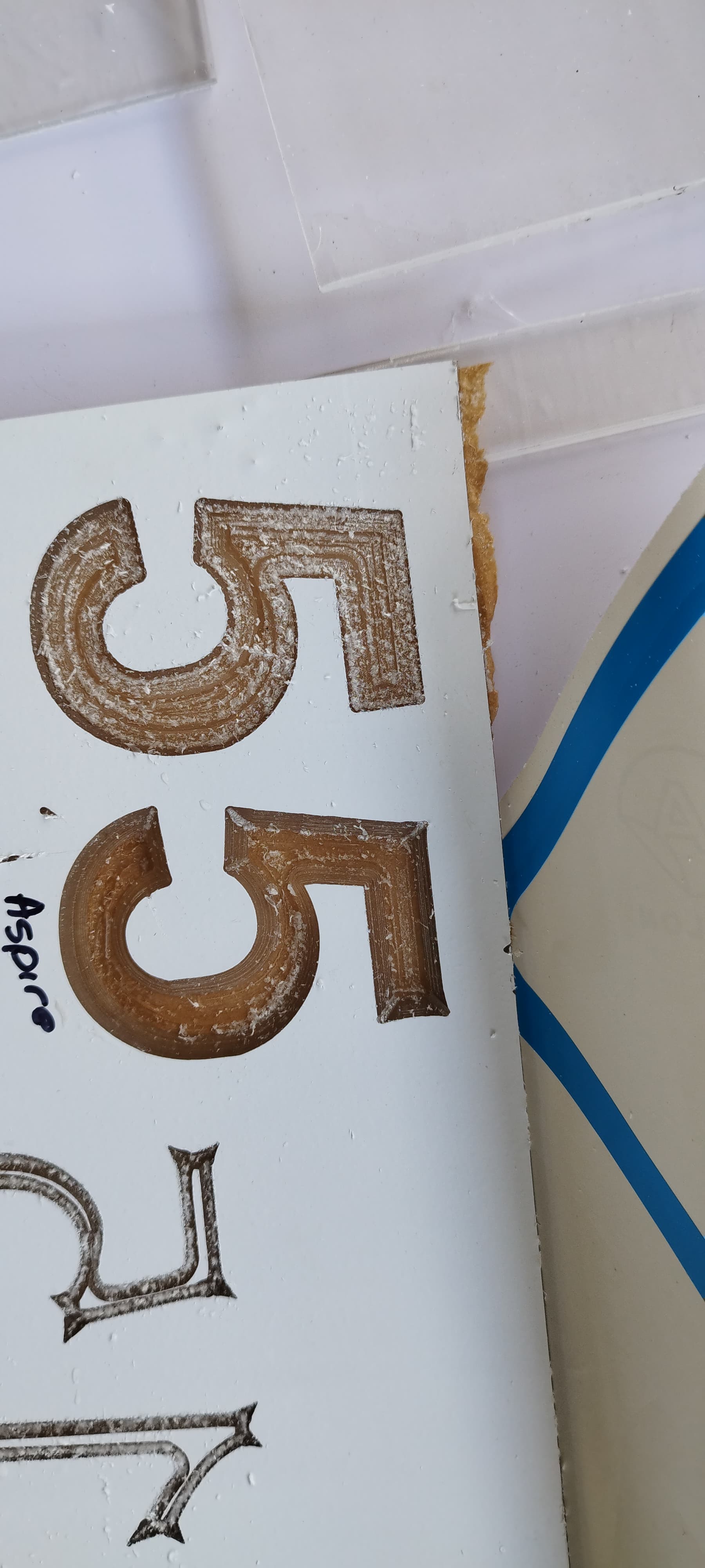
Did some more testing with a bigger bit… I kinda think my problem is software and software settings… Take a look at these pics and let me know what you think
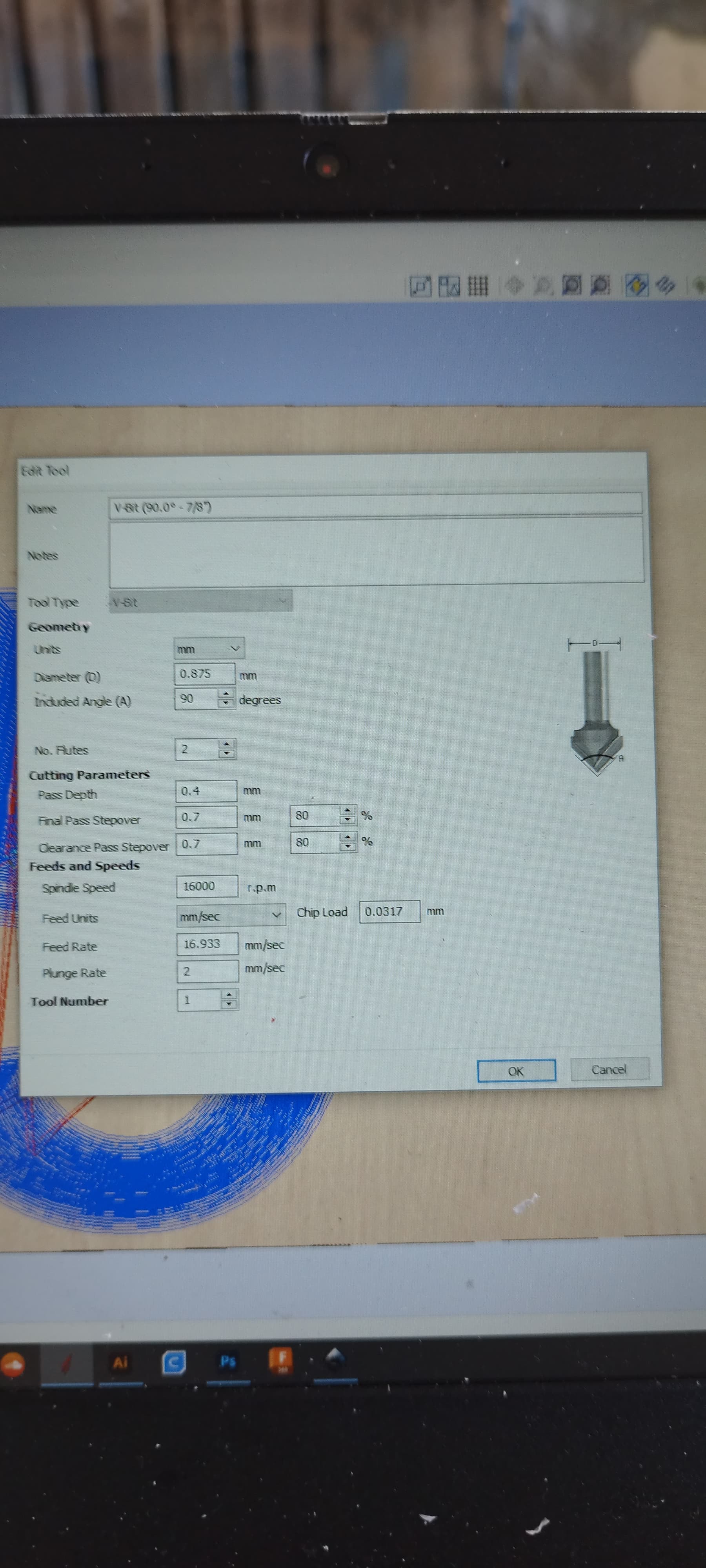
Yes, the 7000 mm / min translates to 116.67 mm / sec — it’s a simple divide by 60 calc.
However, notice there is a slider on the screenshot showing that that recommended speed is on the low end of an acceptable range. I think it’s at 8.7%. So you could take that number 7000, and drop it to 6000 or even 5000 and still be within the accepted range. The challenge is that that number works in concert with the RPM of the router, which can’t be lowered less than its minimum speed of 10,000 RPM.
Also bear in mind, that the bit settings I inputted may not match yours well. I did the best I could. The v-shaped bits pose some interesting challenges. The RPM speed decreases at the center point, while increasing at the perimeter.
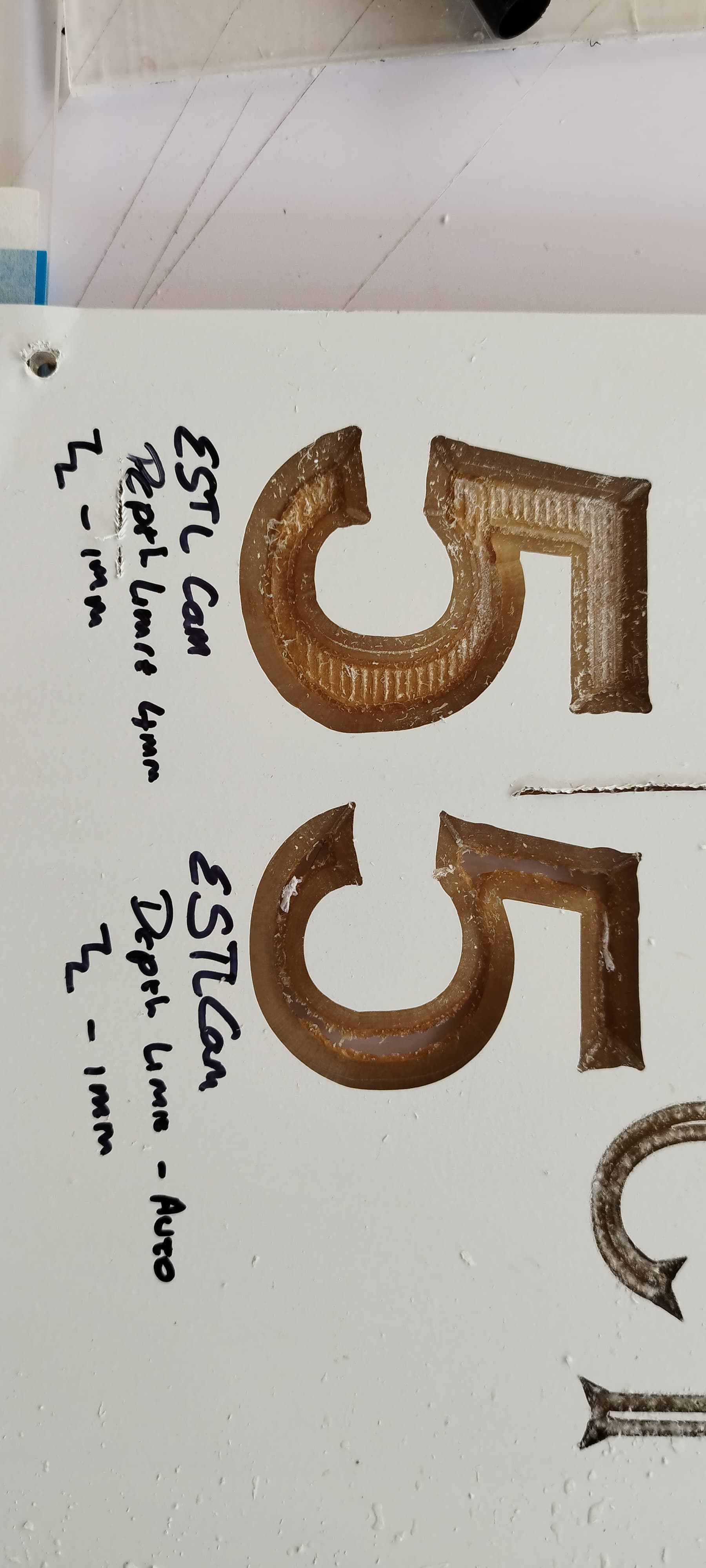
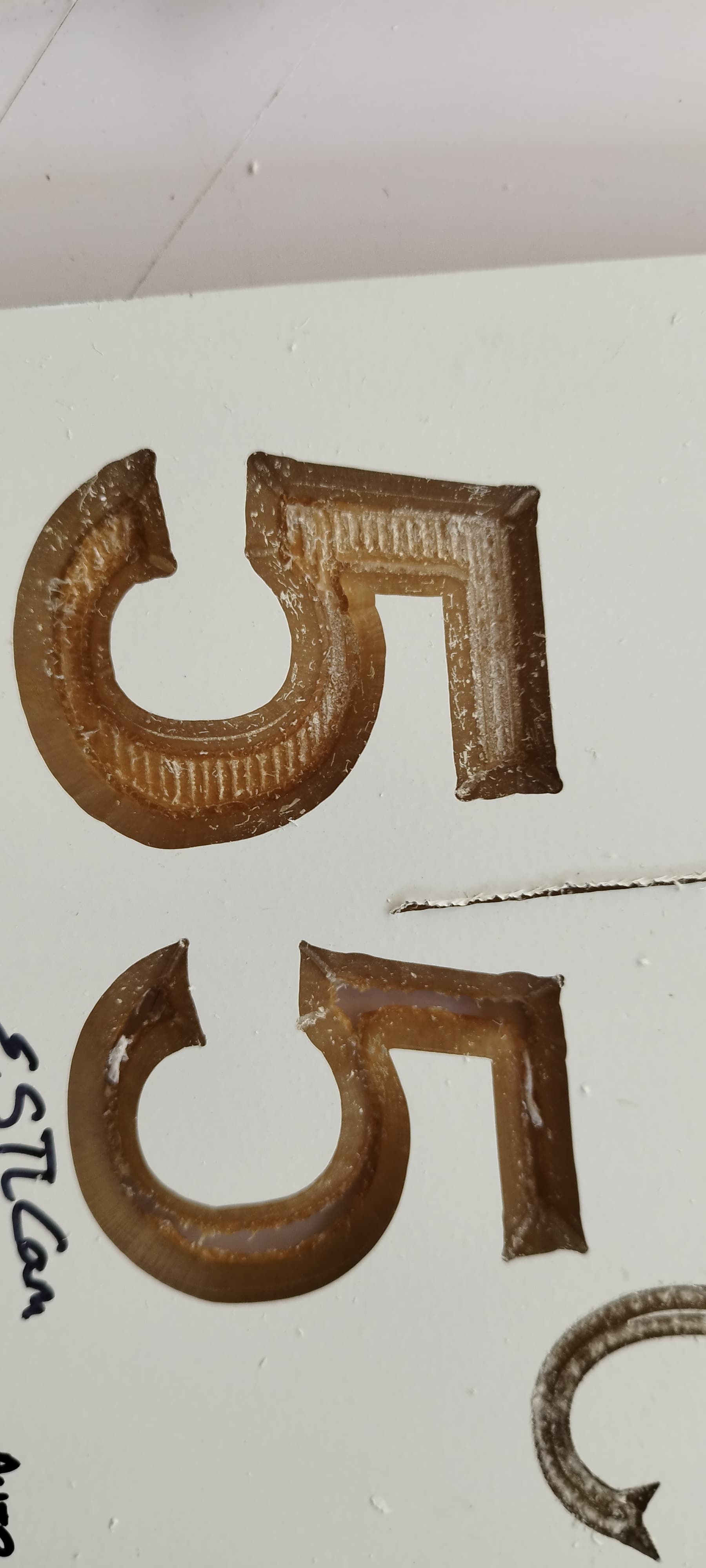
The first ones look like you had some snags. The corners also look like you had the wrong angle for the tip. Estlcam tries to adjust the height to adjust the width. That is dependent on an accurate angle measurement.
The other thing you can do to get a little better results is to pick a sharper bit. With a sharper bit, the error in Z makes a smaller error in XY.
@Np3dprint , like Jeff said I believe the little tails in the corners are due to the CAM software thinking that the cutter angle is larger that it actually is.
There was an old thread that talked about this but unfortunately I can’t find it (it may have been by @jamiek). If I recall correctly, they basically did multiple test runs, slightly changing the v-bit’s angle setting in the CAM software for each run to dial in the actual value. The actual cutter angle will likely be slightly different than the advertised angle due to manufacturing tolerances.
Something like this was actually on my mind, but I was trying to figure out how to calculate the exact angle and depth to cut.
What about the straight edges of the numbers/letters? How to I stop the wobbly lines ? Which seems to be the tool path that estlcam uses … Aspire didn’t have as wobbly lines