My goal with this machine is to develop a product that involves a 600x480mm rectangle with rounded corners, with a large 400mm circle cutout with a stepped layer to place a circle of acrylic that sits flush with the surface (which will also be cut on this).
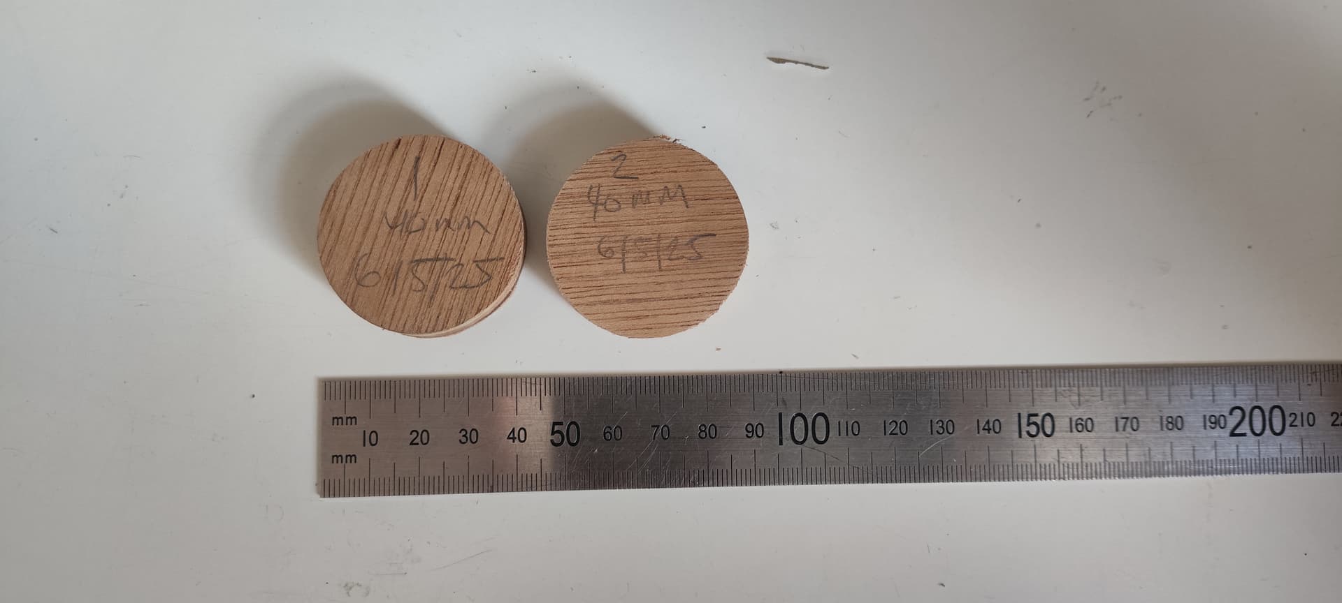
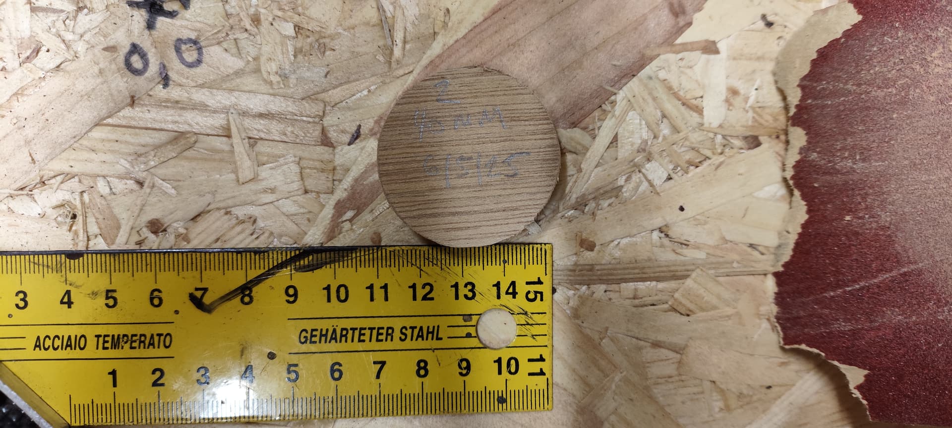
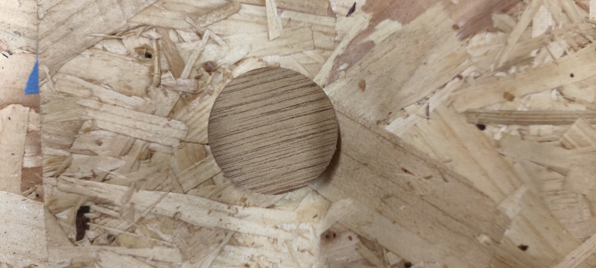
As a test, I’ve been cutting 40mm circles in 12mm ply with a 3mm endmill, and they’re pretty good dimensionally, but I’ve noticed they aren’t quite true circles, which is going to be an issue.
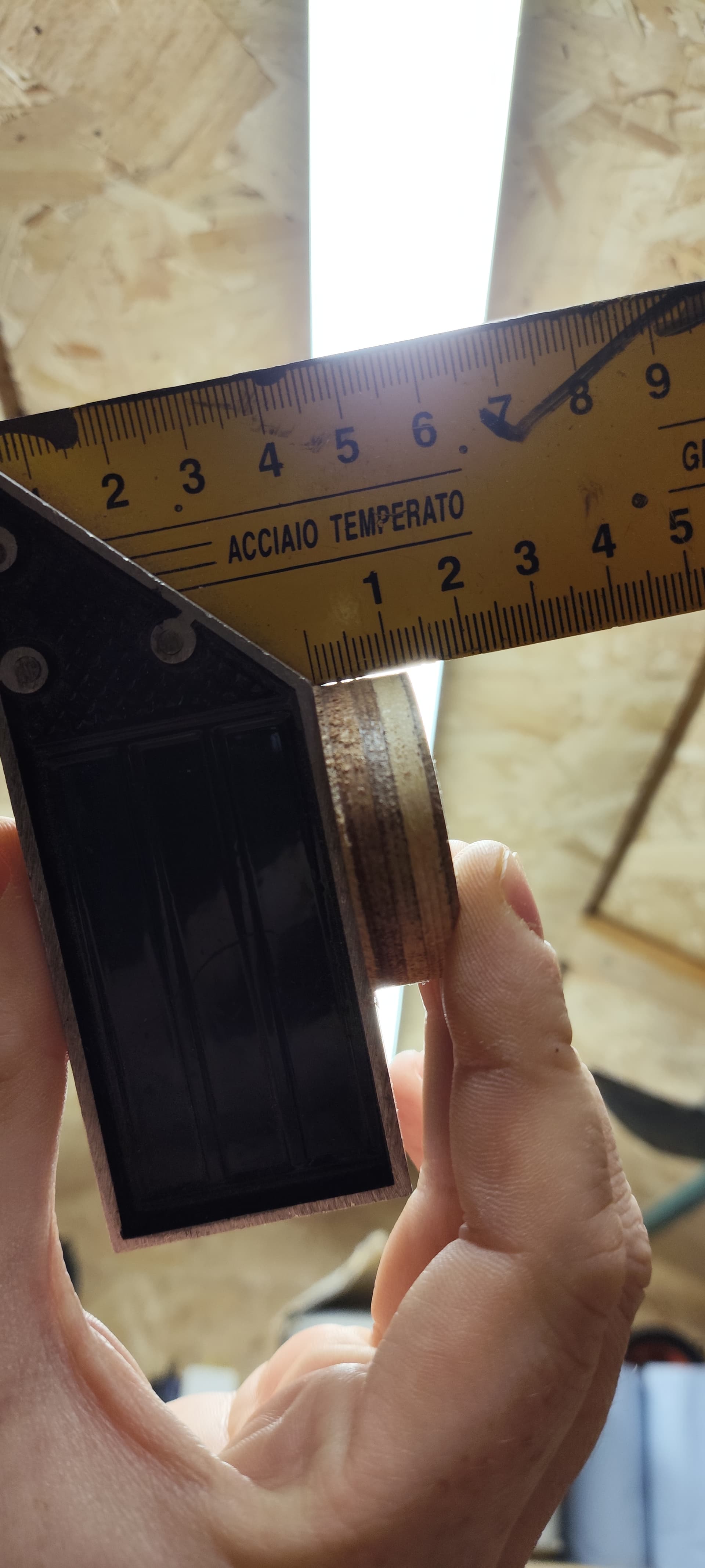
I also noticed that the cuts seem to draft inwards towards the bottom a few degrees, even though in my CAM setup I’ve set cuts to 90º.
I havent fitted my X strut plates yet or my permanent XZ plates, so this could probably account for some of it. This will come soon, but accuracy is important for this too so it’s important to minimise any problems where possible.
Does anyone have any tips on how to get this going more accurately? Things I have in mind:
More XY belt tension
More core tension
Fit strut plates
Better XZ plate rigidity
Would appreciate any advice. Pics for reference.
Also, first broken bit (0.8mm) while trying to mill another crown - achievement unlocked.
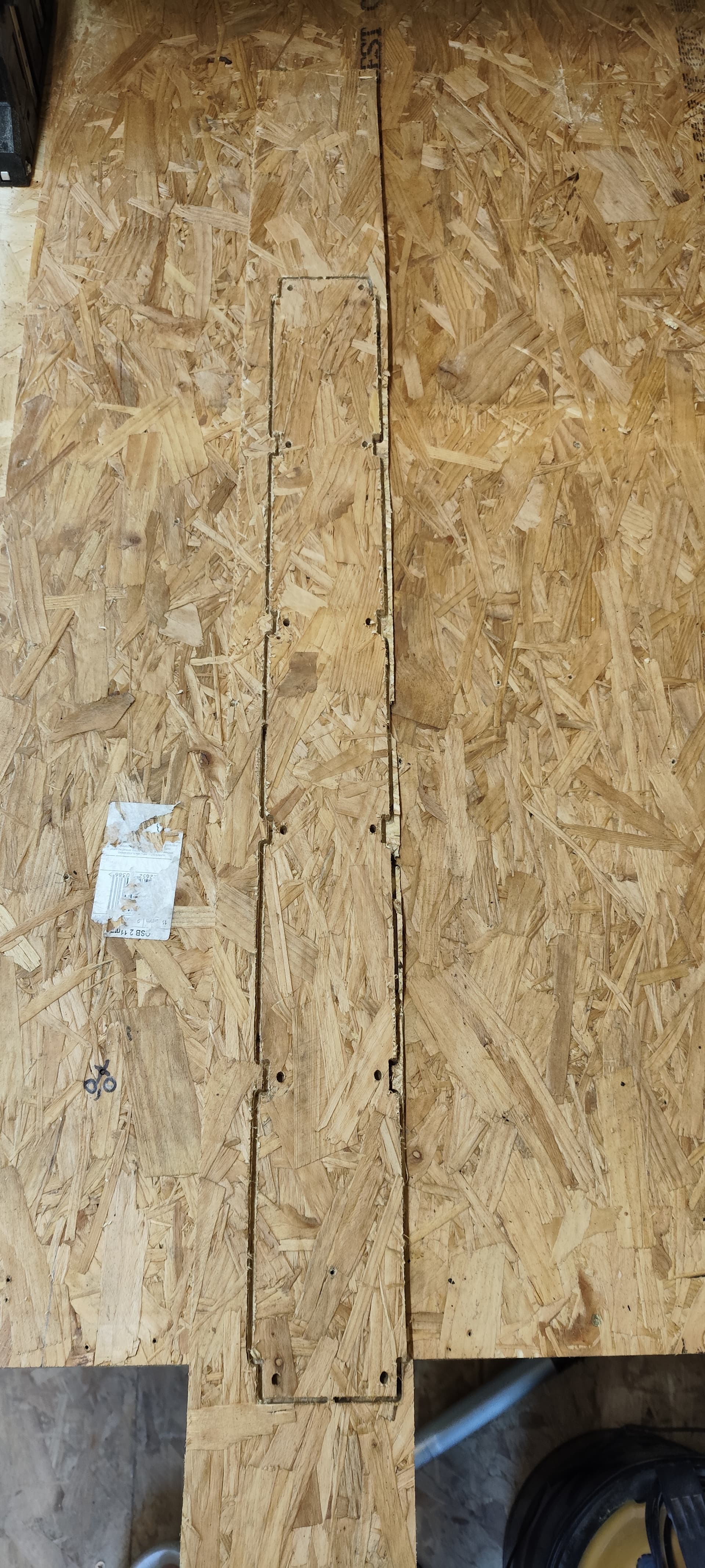
xy dimensions generally pretty accurate, but I notice the holes look very oval.
what should i be doing to stop holes being oval? im thinking belt tension. any other tips?
also i didnt set the DOC properly so its gone in 10mm instead of 12mm which was the actual thickness of the material on closer inspection. but i know how to solve that one.
according to docs I should be using stock around 6.35mm thickness for strut plates. closest suitable bit of MDF i have on hand is 5mm, which should be adequate.
Probably not belt tension unless they are so loose they’re floppy.
Have you tested motion (put down some blue tape, move out to around the machine limits with gcode move commands, and measure how far each move command moves.). Use a v bit to poke holes in the tape for measurement.
So for example if you move the machine 300mm in X and 300mm in Y, how much does it actually move. How repeatable is it?
Edit: Also, with the router off and the Z axis up in the air, push on the router bit and see if you have any significant slop in the machine when you push it +/- X and +/- Y.
I’d say the accuracy of the strut plates isn’t as important as you’re probably thinking – get them cut the best you can now and install them to stiffen up the machine. Cut new ones later if you need to.
What “temporary” XZ plates are you using now, and what are the “permanent” ones going to be made from? You’d save a lot of time by just ordering the aluminum plates from V1.
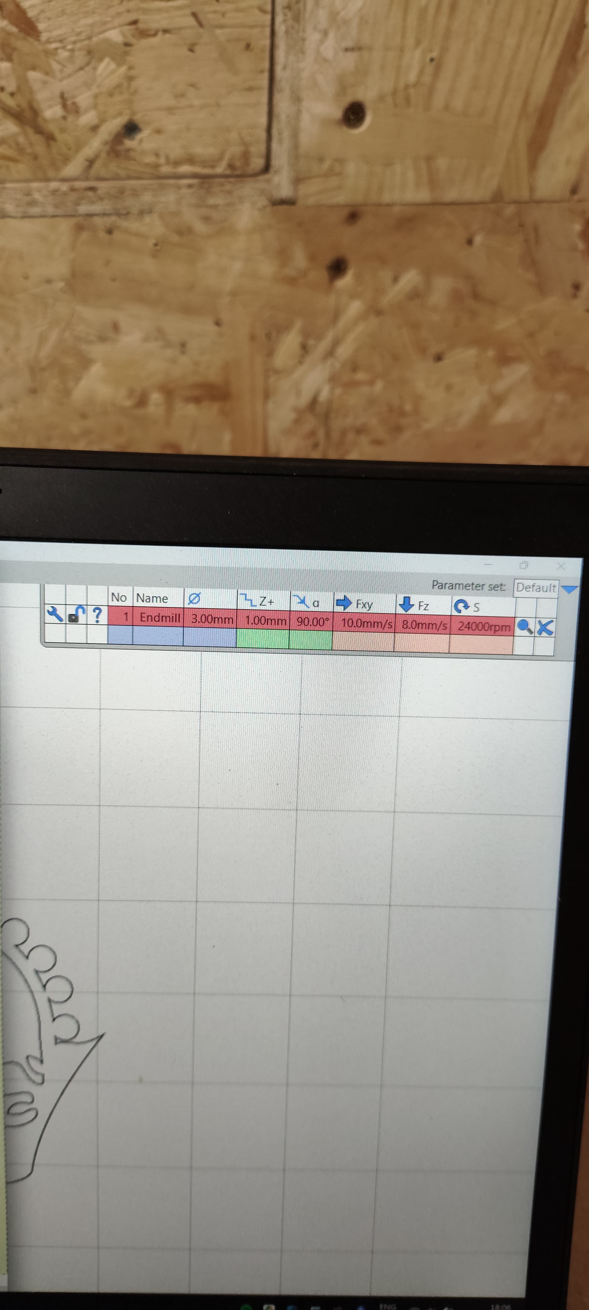
What kind of feeds and speeds and DOC are you using?
You are going to need to be very conservative with this until the machine is stiffened up. 12mm DOC isn’t something I would be trying until the machine is finished being built correctly.